
User Manual

69
Instruction Manual
PSI 8000 3U Series
EN
Date: 03-22-2011
Using the power supply
8. Behaviour of the device when...
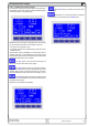
8.1 Switching on by power switch
The power switch is located at the front. After switching on, the
device will show some information in the display: manufacturer‘s
name, address and logo, device type and rmware version. In
the device setup (see section „7. Device conguration“) there is
an option „Power On“ that determines the output condition after
the device is switched on. Default is „OFF“. It means, that the
set values of U, I, P and the output condition are not restored to
what was present when the device was switched off the last time.
In case the option is set to „OFF“, the set values of U and I are
set to 0, the set value of P to 100% and the output is switched
on after every start. With setting „restore“, the set values and
the output condition will be restored when switching the unit on.
8.2 Switching off by power switch
Switching the device off by power switch is handled as mains
blackout. The device will save the last set values and output
condition. After a short time, power output and fans will be
switched off and after a few seconds more, the device will be
completely off.
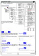
8.3 Switching to remote control
a) By the optional, analogue interface: Pin 22 „SEL-enable“
switches the device to remote control via the set values pins
VSEL (pin 3), CSEL (pin2) and PSEL (pin 1), as well as the
status input REM-SB (pin 13), if not inhibited by LOCAL mode
or remote control by digital interface already being active. The
output condition and the set values which are put into pins 1,
2, 3 and 13 (also see section „10. Analogue interface“) are
immediately set. After return from remote control, the output
will be switched off and the last, remotely adjusted set values
of U, I and P are kept.
b) By an optional, digital interface: Switching to remote control
by the corresponding command (here: object), if not inhibited
by LOCAL mode or remote control via AI already being active,
keeps output state and set values until altered. When returning
from remote control, the last remotely adjusted set values of U,
I P, OVP and the output condition are kept.
8.4 Overvoltage occurs
An overvoltage error can occur due to an internal defect (output
voltage rises uncontrolled) or by a too high voltage from exter-
nal.The overvoltage protection (OVP) will switch off the output
and indicate the error on the display by the status text „OVP“
and an alarm symbol and on the pin 8 „OVP“ of the optional,
analogue interface.
External voltages higher than 120% nominal voltage at the
output must be avoided, or else internal components of the
device might be destroyed!
If the cause of the overvoltage is removed, the output can be
switched on again and status text „OVP“ will disappear. Before
this, the alarm has to be acknowledged by button or by
a command via digital interface. If the error is still present, the
output is not switched on.
OVP errors are recorded as alarm into the internal alarm buffer.
This buffer can be read out via a digital interface. Flushing the
buffer is initiated by another command.
8.5 Overtemperature occurs
As soon as an overtemperature (OT) error occurs by internal
overheating of one or multiple power stages, the status is
indicated in the display by a text „OT“ and an alarm symbol
and on the pin 9 „OT“ of the analogue interface. The output is
not always switched off, depending on the settings (see „7.1.
Dening operation parameters“), and continues to provide
voltage. The output voltage only will only be zero if all internal
power stages (3.3/5kW = 1 stage, 6.6/10kW = 2 stages, 15kW
= 3 stages) have shut down because of overheat.
OT errors have to be acknowledged with pushbutton
or by sending the corresponding command via an optional,
digital interface.
OT errors are recorded as alarm into the internal alarm buffer.
This buffer can be read out via the digital interface. Flushing
the buffer is initiated by another command.
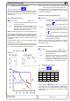
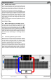
8.6 Voltage, current and power are regulated
The output voltage of the power supply and the resistance of
the load determine the output current. If this current is lower
than the current limitation set by the current set value, then the
device is working in constant voltage (CV) regulation, indicated
by the status text „CV“.
If the output current is limited by the current set value or by the
nominal current, the device will change to constant current (CC)
regulation mode, indicated by the status text „CC“.
All models feature an adjustable power limitation for 0...P
Nom
.
It becomes active and overrides constant voltage or constant
current regulation mode, if the product of actual current and
actual voltage exceeds the adjusted power limitation. The power
limitation primarily affects the output voltage. Because voltage,
current and power limitation affect each other, various situations
like these may occur:
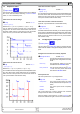
Example 1: the device is in constant voltage regulation, then the
power is limited down. As a result, the output voltage is decre-
ased. A lower output voltage results in a lower output current.
In case the resistance of the load is then decreased, the output
current will rise again and the output voltage will sink further.
Example 2: the device is in constant current regulation, the
output voltage is dened by the resistance of the load. Then
the power is limited down. Output voltage and current are
decreasing to values according to the formula P = U * I. Once
the current set value is decreased, the output current would
also decrease and thus the output voltage. The product of both
values, the actual power, would sink below the previously set
power limit and the device would change from constant power
regulation (CP) to constant current regulation (CC).
Those three conditions CC, CV and CP are also indicated on the
appropriate pins of the optional, analogue interface cards or can
be read out as status bits via an optional, digital interface card.