
User Manual

57
Instruction Manual
PSI 8000 3U Series
EN
Date: 03-22-2011
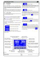
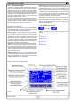
Using predened set values
A table of up to 4 sets of set values is accessible in the menu
Preset List (see „7.2. Predening preset lists“). The left knob
selects the preset list and with the RETURN button the set is
submitted or discarded with the ESC button.
The chosen set is still 1. After the RETURN button
is pressed, the set values of set 3 are submitted to the power
supply. The display then shows the new set values of set 3.
The ORY button can be used to jump straight to the
menu page where the preset lists are dened and there they‘re
edited and submitted with RETURN as usual.
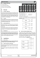
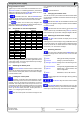
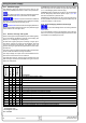
6.6 Step widths for set value adjustment
Voltage Current
Nom. val Coarse Fine Nom. val Coarse Fine
40V 0.25V 10mV 30A 0.2A 10mA
80V 0.5V 10mV 60A 0.5A 10mA
160V 1V 0.1V 70A 0.5A 10mA
200V 2V 0.1V 90A 1A 10mA
240V 2V 0.1V 170A 1A 0.1A
400V 2V 0.1V 210A 2A 0.1A
500V 5V 0.1V 340A 2A 0.1A
600V 5V 0.1V 510A 5A 0.1A
1000V 10V 1V
1500V 10V 1V
Power
Nom. val Coarse Fine
3.3/5kW 0.050kW 0.001kW
6.6/10kW 0.10kW 0.01kW
15kW 0.10kW 0.01kW
Important! The resolution of the set value adjustment in some
cases is, depending on the nominal values, higher than the one
of the output voltage. Thus it can happen that the output voltage
only changes every 2 or 3 steps.
6.7 Switching the button panel
The button PAGE is used to switch to another button
panel. The new button assignments of the other panel allow the
user to lock the control panel, switch to the function manager
or set the location mode.
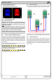
6.8 Locking the control panel
The button „Lock button panel“ locks all buttons, except
itself, and the rotary knobs. The unit is now locked from manu-
al acess, so that no set value can be changed or no menu is
accessible. The locking mode can be set up in the menu. The
control panel can be either completely inactive or it can exclude
the OFF button (the unit is then locked but can be switched off
and on by the OFF button). See also „Control panel lock“ in
section „7.4. Conguring the control panel“.
After the control panel was locked it changes to this
icon. The button can be used to unlock the control panel again,
if button
is pressed within 2s.
6.9 Changing the location mode
The unit can be set up to a location mode which doesn’t allows
it to be remotely controlled or switched to remote control by an
interface card.
With the button EXT the user enables the remote control
of the unit via an digital or analogue interface card and disables
the local mode.
With this button the user sets the unit into strict local
mode, so that it is only controllable locally (local), means by
hand and access by any interface, analogue or digital, is denied.
6.10 Switching to the function manager
The SEQ button switches the display to the function
manager mode.
Switching to the function manager is only possible while the unit
is in standby (output = off). The set values of voltage and current
are set to 0V and 0A. For details about the function manager
see section „6.15. The function manager“.
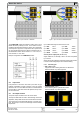
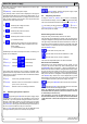
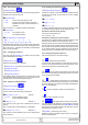
6.11 Activating the menu
The main menu is acessed with the MENU button and
the display changes to the main menu level. A text menu like
this appears:
Prole
Setting up and selecting user proles
Function Setting up a function sequence
Analogue interface
Settings for the internal analogue inter-
face
Communication Congure the pluggable interface card
Options Default setup, unlock features, lock
device conguration
About… Ma
nufacturer, service, SW version etc.
A menu page is left to the next higher level by pressing
the ESC button.
The SELECT keys are used to select another
menu entry.
The RETURN button then enters the menu entry into
the next sublevel by pressing it. The lowest menu level always
shows up as a parameter page. See next topic for details.
Using the power supply