
User Manual

56
© 2006, Elektro-Automatik GmbH & Co. KG
Irrtümer und Änderungen vorbehalten
EN
Instruction Manual
PSI 8000 3U Series
Date: 03-22-2011
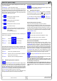
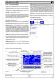
About the power supply
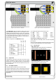
The state of the power output is displayed in the bottom right
corner of the display.
{ON,OFF} State of the power output
The presently active control mode is displayed to the right of
the related actual values. For instance, the abbreviation „CV“ is
displayed next to the actual value of voltage, because it means
that „Constant voltage“ mode is active. The output values are
limited by the active control mode:
- limited by the voltage set value
(= Constant Voltage)
- limited by the power set values
(= Constant Power)
- limited by the set value of current
(= Constant Current)
- limited by the set value for internal resistance
(optional at U/I/R mode), indicated next to the
actual voltage
(= Constant Resistance)
Additionally to the state of the output an alarm, a warning or a
signal can be displayed:
Alarm Example: = Overtemperature
Warnings Example: = Overvoltage
Signals Example: = Overcurrent
The location from where the unit is currently controlled is dis-
played below the output state. This location is absolute, which
means that you cannot control the unit from elsewhere without
changing the location.
local Control only possible at the unit
remote Remote control via communication interfaces
(IF-C1, IF-R1, IF-U1 etc.)
extern Remote control via analogue interface
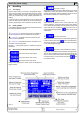
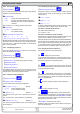
6.4 Switching the power output on
By pressing the ON button the power supply output
is switched on, as long as it is not overridden by the input pin
„REM-SB“ (13) of the optional analogue interface card IF-A1,
because it has higher priority. If so and when trying to switch
the output on by the button, the display will indicate the status
text „auto ON“, noticing the user that the output will switch on
as soon as the override from the pin is removed.
Note: in local state (see section 6.9), the pin REM-SB of the
analogue interface (internal or external) is inoperative.
The display shows the current state with „ON“.
The OFF button switches the power supply output
off. This state is displayed with „OFF“.
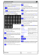
6.5 Adjusting set values
As long as „extern“ or „remote“ are not shown in the display,
the set values for voltage, current or power can be set manually.
The mode is selected in the device setup at Accept set va-
lue. The setting can be accessed with -> Prole ->
General settings -> Control panel. See „7.4. Conguring
the control panel“ for details.
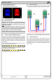
Direct setting of the set values
Using the rotary knobs directly sets the set values.
The left rotary knob adjusts the voltage. The set value of the
voltage is displayed invertedly while it is selected and adjusted.
The right rotary knob either sets the set value for the current, for
the power or internal resistance (optional, unlockable, with U/I/R
mode chosen). The selected set value is displayed invertedly.
With the SELECT keys
the set value for the power, with
the set value for the internal resistance or with
the set value for the current is selected.
The maximum adjustable power can also be limited.
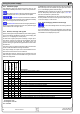
Set values are submitted
Alternatively to the direct adjustment of set values you can
choose to set the set values only after submitting them with
the RETURN button. See section „7. Device conguration“ for
details. The set values can still be changed with the rotary knobs,
but are not set to the output as long as they’re not submitted.
While the set value is unchanged, only its unit is displayed inver-
tedly. If the set value is changed it is also displayed invertedly.
The SELECT keys switch from current adjustment to power
adjustment for the right rotary knob. The chosen set values are
not submitted to and set by the power supply until then.
Pressing the RETURN button submits the set values.
Pressing the ESC button discards the new set values
and the old set values are displayed again.
Note: the adjustment of the resistance set value is only
accessible after the optional „internal resistance control“
is unlocked (see section 7.8).
The resistance set value is adjustable from 0Ω up to
20* Unom/Inom. Means, for example, at a device with Unom
= 65V and Inom = 10A it can be adjusted to a maximum of
130Ω.