
User Manual

53
Instruction Manual
PSI 8000 3U Series
EN
Date: 03-22-2011
About the device
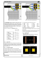
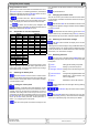
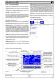
The 6.6kW/10kW models are different. Phase L2(S) is here
loaded with 28A by already one unit. In this case it is recom-
mended to alter the phase mapping. It means, not to necessarily
connect phase L1(R) to the L1 input of the unit‘s input terminal
etc. The example below shows an almost symmetric input cur-
rent distribution scheme which results in L1 = max. 44A, L2 =
max. 56A and L3 = max. 60A.
Example conguration for 6.6kW/10kW models:
5.4 Input fuses
Fuse protection of the unit is done with up to 6 fuses of type
Littlefuse F16A/500V and size 6.3x32mm. They are located
inside the unit on a mains lter board which is located behind
the front plate. In case fuses need to be replaced, the top cover
has to be removed.
5.5 DC output terminal
The power output is located on the rear of the device.
The output is not fused! In order to avoid damage to the load
application, always take care for the nominal values of the load.
The cross section of the load leads depends on several condi-
tions, like the output current, the lead length and the ambient
temperature.
Figure 6. Input connection 3.3kW/5kW Figure 7. Input connection 6.6kW/10kW/15kW
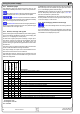
Up to 1.5m cable length we recommend to use:
up to 30A: 6mm² up to 70A: 16mm²
up to 90A: 25mm² up to 140A: 50mm²
up to 170A: 70mm² up to 210A: 95mm²
up to 340A: 2x70mm² up to 510A: 2x120mm²
at least per DC output pole (exible wire).
Single cables like, for example, 70mm² can also be replaced
by 2x 35mm².
When using longer cables it is required to increase cross section
in order to avoid voltage drops and unwanted heating.
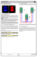
5.5.1 Terminal types
• 40V or 80V models:
Copper bars with 3x drilling holes 9mm for M8 screws
Recommendation: ring cable lugs 8mm
• 160V/200V/240V models:
Screw fastening M8 on a plastic DC terminal
Recommendation: ring cable lugs 8mm