
User Manual


Page 25
EA Elektro-Automatik GmbH
Helmholtzstr. 31-33 • 41747 Viersen
Germany
Fon: +49 2162 / 3785-0
Fax: +49 2162 / 16230
www.elektroautomatik.de
ea1974@elektroautomatik.de
PS 9000 3U Series
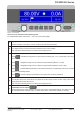
This area furthermore displays various status texts:
Display Description
Locked The HMI is locked
Remote The device is under remote control from...
Analog ...the built-in analog interface
USB ...the built-in USB port or a plug in interface module
Ethernet ...the built-in Ethernet/LAN port
Local The device has been locked by the user explicitly against remote control
Alarm: OT etc. Alarm condition which has not been acknowledged or still exists
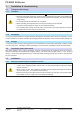
1.10.6.2 Rotary knobs
As long as the device is in manual operation, the two rotary knobs are used to adjust set values, as well as
setting the parameters in the settings menu . For a detailed description of the individual functions see section „3.3
Manual operation“ on page 37. Both rotary knobs have an additional pushbutton function whereby the decimal
position of the value to be set is moved. In this way, for example, the set current value for a device with nominal
510 A can be adjusted in increments of 10 A or possibly 0.1 A. (also see 1.10.6.4)
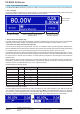
1.10.6.3 Button function of the rotary knobs
The rotary knobs also have a pushbutton function which is used in all menu options for value adjustment to move
the cursor by rotation as shown:
1.10.6.4 Resolution of the displayed values
In the display, set values can be adjusted in variable increments. The number of decimal places depends on the
device model. The values have 3 to 5 digits. Actual and set values always have the same number of digits.
Adjustment resolution and number of digits of set values in the display:
Voltage,
OVP, U-min, U-max
Current,
OCP, I-min, I-max
Power,
OPP, P-max
Nominal
Digits
Min. incre-
ment
Nominal
Digits
Min. incre-
ment
Nominal
Digits
Min. incre-
ment
40 V / 80 V 4 0.01 V 20 A / 30 A 4 0.01 A 3.3 kW 3 0.01 kW
200 V 5 0.01 V 40 A / 60 A 4 0.01 A 5 kW 3 0.01 kW
360 V / 500 V 4 0.1 V 70 A / 80 A 4 0.01 A 6.6 kW 3 0.01 kW
750 V 4 0.1 V 90 A 4 0.01 A 10 kW 4 0.01 kW
1000 V 5 0.1 V 120 A / 140 A 4 0.1 A 15 kW 4 0.01 kW
1500 V 5 0.1 V 210 A 4 0.1 A
340 A 4 0.1 A
510 A 4 0.1 A
In manual operation every set value can be set in the increments given above. In this case
the actual output values set by the device will lie within percentage tolerances as shown in the
technical data sheets. These will inuence the actual values.