Elektro-Automatik GmbH Betriebsanleitung PS 9000 3U DC-Hochleistungs-Netzgerät Doc ID: PS93UDE Revision: 02 Date: 04/2014
PS 9000 3U Serie INHALT 1 ALLGEMEINES 1.1 1.1.1 1.1.2 1.1.3 1.2 1.3 1.4 1.5 1.6 1.7 1.8 1.8.1 1.8.2 1.8.3 1.8.4 1.8.5 1.9 1.9.1 1.9.2 1.9.3 1.9.4 1.10 1.10.1 1.10.2 1.10.3 1.10.4 1.10.5 1.10.6 1.10.7 1.10.8 1.10.9 1.10.10 1.10.11 2 Zu diesem Dokument.....................................5 Aufbewahrung und Verwendung....................5 Urheberschutz (Copyright).............................5 Geltungsbereich..............................................5 Symbolerläuterungen...............................
PS 9000 3U Serie 4.4.2 4.4.3 Vorbereitung..................................................58 Abgleichvorgang...........................................58 5 ZUBEHÖR UND OPTIONEN 6 SERVICE & SUPPORT 5.1 Übersicht.......................................................60 6.1 6.2 Seite 4 Übersicht.......................................................60 Kontaktmöglichkeiten ..................................60 EA Elektro-Automatik GmbH Helmholtzstr.
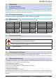
PS 9000 3U Serie 1. Allgemeines 1.1 Zu diesem Dokument 1.1.1 Aufbewahrung und Verwendung Dieses Dokument ist für den späteren Gebrauch und stets in der Nähe des Gerätes aufzubewahren und dient zur Erläuterung des Gebrauchs des Gerätes. Bei Standortveränderung und/oder Benutzerwechsel ist dieses Dokument mitzuliefern und bestimmungsgemäß anzubringen bzw. zu lagern. 1.1.
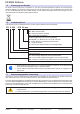
PS 9000 3U Serie 1.5 Entsorgung des Gerätes 1.6 Produktschlüssel Ein Gerät, das zur Entsorgung vorgesehen ist, muß laut europaweit geltenden Gesetzen und Verordnungen (ElektroG, WEEE) vom Hersteller zurückgenommen und entsorgt werden, sofern der Betreiber des Gerätes oder ein von ihm Beauftragter das nicht selbst erledigt.
PS 9000 3U Serie 1.8 Sicherheit 1.8.1 Sicherheitshinweise Lebensgefahr - Gefährliche Spannung • Beim Betrieb elektrischer Geräte stehen zwangsweise bestimmte Teile unter teils gefährlicher Spannung, mit Ausnahme der 40 V-Modelle gemäß SELV.
PS 9000 3U Serie 1.8.3 Pflichten des Betreibers Betreiber ist jede natürliche oder juristische Person, die das Gerät nutzt oder Dritten zur Anwendung überläßt und während der Nutzung für die Sicherheit des Benutzers, des Personals oder Dritter verantwortlich ist. Das Gerät wird im gewerblichen Bereich eingesetzt. Der Betreiber des Gerätes unterliegt daher den gesetzlichen Pflichten zur Arbeitssicherheit.
PS 9000 3U Serie 1.8.5 Alarmsignale Das Gerät bietet diverse Möglichkeiten der Signalisierung von Alarmsituationen, jedoch nicht von Gefahrensituationen. Die Signalisierung kann optisch (auf der Anzeige als Text), akustisch (Piezosummer) oder elektronisch (Pin/Meldeausgang an einer analogen Schnittstelle) erfolgen. Alle diese Alarme bewirken die Abschaltung des DC-Ausgangs.
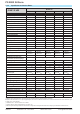
PS 9000 3U Serie 1.9.3 Spezifische technische Daten 3,3 kW / 5 kW Modell 3U PS 9040-170 PS 9080-170 PS 9200-70 PS 9360-40 PS 9500-30 AC-Eingang Netzspannung 340...460 V AC 340...460 V AC 340...460 V AC 340...460 V AC 340...
PS 9000 3U Serie 3,3 kW / 5 kW Modell 3U PS 9040-170 PS 9080-170 PS 9200-70 PS 9360-40 PS 9500-30 Steuereingänge U, I, P U, I, P U, I, P U, I, P U, I, P Monitorausgänge U, I DC ein/aus, Fernst. ein/aus CV, OVP, OT Max. 1500 V DC U, I DC ein/aus, Fernst. ein/aus CV, OVP, OT Max. 1500 V DC U, I DC ein/aus, Fernst. ein/aus CV, OVP, OT Max. 1500 V DC U, I DC ein/aus, Fernst. ein/aus CV, OVP, OT Max. 1500 V DC U, I DC ein/aus, Fernst. ein/aus CV, OVP, OT Max.
PS 9000 3U Serie 5 kW / 6,6 kW / 10 kW Modell 3U PS 9750-20 PS 9040-340 PS 9040-510 PS 9080-340 PS 9200-140 AC-Eingang Netzspannung 340...460 V AC 340...460 V AC 340...460 V AC 340...460 V AC 340...
PS 9000 3U Serie 5 kW / 6,6 kW / 10 kW Modell 3U PS 9750-20 PS 9040-340 PS 9040-510 PS 9080-340 PS 9200-140 Steuereingänge U, I, P U, I, P U, I, P U, I, P U, I, P Monitorausgänge U, I DC ein/aus, Fernst. ein/aus CV, OVP, OT Max. 1500 V DC U, I DC ein/aus, Fernst. ein/aus CV, OVP, OT Max. 1500 V DC U, I DC ein/aus, Fernst. ein/aus CV, OVP, OT Max. 1500 V DC U, I DC ein/aus, Fernst. ein/aus CV, OVP, OT Max. 1500 V DC U, I DC ein/aus, Fernst. ein/aus CV, OVP, OT Max.
PS 9000 3U Serie 10 kW / 15 kW Modell 3U PS 9360-80 PS 9500-60 PS 9750-40 PS 91000-30 PS 9080-510 AC-Eingang Netzspannung 340...460 V AC 340...460 V AC 340...460 V AC 340...460 V AC 340...
PS 9000 3U Serie 10 kW / 15 kW Modell 3U PS 9360-80 PS 9500-60 PS 9750-40 PS 91000-30 PS 9080-510 Steuereingänge U, I, P U, I, P U, I, P U, I, P U, I, P Monitorausgänge U, I DC ein/aus, Fernst. ein/aus CV, OVP, OT Max. 1500 V DC U, I DC ein/aus, Fernst. ein/aus CV, OVP, OT Max. 1500 V DC U, I DC ein/aus, Fernst. ein/aus CV, OVP, OT Max. 1500 V DC U, I DC ein/aus, Fernst. ein/aus CV, OVP, OT Max. 1500 V DC U, I DC ein/aus, Fernst. ein/aus CV, OVP, OT Max.
PS 9000 3U Serie Modell 3U 15 kW PS 9200-210 PS 9360-120 PS 9500-90 PS 9750-60 PS 91500-30 AC-Eingang Netzspannung 340...460 V AC 340...460 V AC 340...460 V AC 340...460 V AC 340...
PS 9000 3U Serie 15 kW Modell 3U PS 9200-210 PS 9360-120 PS 9500-90 PS 9750-60 PS 91500-30 Steuereingänge U, I, P U, I, P U, I, P U, I, P U, I, P Monitorausgänge U, I DC ein/aus, Fernst. ein/aus CV, OVP, OT Max. 1500 V DC U, I DC ein/aus, Fernst. ein/aus CV, OVP, OT Max. 1500 V DC U, I DC ein/aus, Fernst. ein/aus CV, OVP, OT Max. 1500 V DC U, I DC ein/aus, Fernst. ein/aus CV, OVP, OT Max. 1500 V DC U, I DC ein/aus, Fernst. ein/aus CV, OVP, OT Max.
PS 9000 3U Serie Ansichten A - Netzschalter B - Bedienteil C - Steuerungsschnittstellen (digital, analog) D - Share-Bus- und Fernfühlungsanschlüsse E - DC-Ausgang (Abb. zeigt Anschlußtyp 1) F - Netzanschluß 1.9.4 Bild 1 - Vorderseite Seite 18 Bild 2 - Rückseite EA Elektro-Automatik GmbH Helmholtzstr. 31-33 • 41747 Viersen Telefon: 02162 / 3785-0 Telefax: 02162 / 16230 www.elektroautomatik.de ea1974@elektroautomatik.
Bild 3 - Seiteansicht von links Bild 4 - Seitenansicht von rechts PS 9000 3U Serie EA Elektro-Automatik GmbH Helmholtzstr. 31-33 • 41747 Viersen Telefon: 02162 / 3785-0 Telefax: 02162 / 16230 www.elektroautomatik.de ea1974@elektroautomatik.
PS 9000 3U Serie Bild 5 - Ansicht von oben Seite 20 EA Elektro-Automatik GmbH Helmholtzstr. 31-33 • 41747 Viersen Telefon: 02162 / 3785-0 Telefax: 02162 / 16230 www.elektroautomatik.de ea1974@elektroautomatik.
PS 9000 3U Serie Bild 6 - Bedienfeld Übersicht der Bedienelemente am Bedienfeld Für eine genaue Erläuterung siehe Abschnitt „1.10.6. Die Bedieneinheit (HMI)“. (1) Anzeige Dient zur Anzeige von Sollwerten, Menüs, Zuständen, sowie Istwerten und Status.
PS 9000 3U Serie 1.10 Aufbau und Funktion 1.10.1 Allgemeine Beschreibung Die elektronischen Hochleistungsnetzgeräte der Serie PS 9000 3U sind durch ihre recht kompakten 19“-Einschubgehäuse mit 3 Höheneinheiten (3U) besonders für Prüfsysteme und Industriesteuerungen geeignet. Für die Fernsteuerung per PC oder SPS verfügt das Gerät serienmäßig über eine rückwärtige USB-B-Schnittstelle, eine Ethernetschnittstelle, sowie eine Analogschnittstelle.
PS 9000 3U Serie 1.10.3 Lieferumfang 1 x Netzgerät 1 x Gedruckte Betriebsanleitung 1 x Stecker für Share-Bus (aufgesteckt oder beiliegend) 1 x Stecker für Fernfühlung (aufgesteckt oder beiliegend) 1 x USB-Kabel 1,8 m 1 x Set DC-Klemmenabdeckung 1 x CD „Drivers & Tools“ 1.10.4 Zubehör CABINET 19“-Schränke 1.10.5 Schränke sind in diversen Konfigurationen bis 42 HE als Parallelschaltungssystem verfügbar, auch gemischt mit elektronischen Lasten, um Testsysteme zu realisieren.
PS 9000 3U Serie 1.10.6 Die Bedieneinheit (HMI) HMI steht für Human Machine Interface, auf deutsch Mensch-Maschine-Schnittstelle, und besteht hier aus einer Anzeige, zwei Drehknöpfen mit Tastfunktion und sechs Drucktasten. 1.10.6.1 Anzeige Die grafische Anzeige ist in mehrere Bereiche aufgeteilt.
PS 9000 3U Serie Dieses Feld zeigt weiterhin diverse Statustexte an: Anzeige Beschreibung Gesperrt Das HMI ist gesperrt Fern Das Gerät befindet sich in Fernsteuerung durch... Analog ...die eingebaute Analogschnittstelle USB ...die eingebaute USB-Schnittstelle Ethernet ...die eingebaute Ethernet/LAN-Schnittstelle Lokal Das Gerät ist durch Benutzereingabe explizit gegen Fernsteuerung gesperrt worden Alarm: OT usw.
PS 9000 3U Serie 1.10.7 USB-Port (Rückseite) Der USB-Port Typ B auf der Rückseite des Gerätes dient zur Kommunikation mit dem Gerät, sowie zur Firmwareaktualisierung. Über das mitgelieferte USB-Kabel kann das Gerät mit einem PC verbunden werden (USB 2.0, USB 3.0). Der Treiber wird auf CD mitgeliefert bzw. ist als Download verfügbar und installiert einen virtuellen COM-Port. Details zur Fernsteuerung sind in weiterer Dokumentation auf der Webseite des Geräteherstellers bzw.
PS 9000 3U Serie 1.10.10 Share-Bus-Anschluß Diese auf der Rückseite des Gerätes befindliche, 2polige WAGO-Buchse („Share“) dient zur Verbindung mit der gleichnamigen Buchse an kompatiblen Netzgeräten, um in Parallelschaltung von bis zu 10 gleichartigen Geräten eine gleichmäßigen Laststromaufteilung zu erreichen. Sie dient auch zur Verbindung mit dem Share-Anschluß kompatibler elektronischer Lasten, um einen Zwei-Quadranten-Betrieb herzustellen.
PS 9000 3U Serie 2. Installation & Inbetriebnahme 2.1 Transport und Lagerung 2.1.1 Transport • Die Griffe an der Vorderseite des Gerätes dienen nicht zum Tragen! • Das Gerät sollte aufgrund seines Gewichts und je nach Modell möglichst nicht per Hand transportiert werden bzw.
PS 9000 3U Serie 2.3.2 Vorbereitung Für den netzseitigen Anschluß des Netzgerätes der Serie PS 9000 3U ist ein 5poliger Anschlußstecker auf der Rückseite vorgesehen (im Lieferumfang enthalten). Für die Verkabelung des Steckers ist eine mindestens 3polige (L2+L3+PE), je nach Modell auch bis zu 4polige Zuleitung (L1+L2+L3+PE) mit entsprechendem Querschnitt und Länge vorzusehen. Für Empfehlungen zum Querschnitt siehe „2.3.4. Anschluß an das Stromnetz (AC)“.
PS 9000 3U Serie 2.3.4 Anschluß an das Stromnetz (AC) • Der Anschluß an eine AC-Stromversorgung darf nur durch entsprechend geschultes Personal erfolgen! • Dimensionieren Sie den Querschnitt von Anschlußleitungen entsprechend des maximalen Eingangsstromes des Gerätes (siehe Tabelle)! • Stellen Sie vor dem Anstecken des Netzanschlußsteckers sicher, daß das Gerät am Netzschalter ausgeschaltet ist! Das Gerät wird mit einem 5poligen Netzanschlußstecker geliefert.
PS 9000 3U Serie 2.3.5 Anschluß von DC-Lasten • Bei einem Gerät mit hohem Nennstrom und demzufolge entsprechend dicken und schweren DC-Anschlußleitungen sind das Gewicht der Leitungen und die Belastung des DC-Anschlusses am Gerät zu beachten und besonders bei Installation des Gerätes in einem 19"-Schrank oder ähnlich, wo die Leitungen am DC-Ausgang hängen, Zugentlastungen anzubringen. • Anschließen und Betrieb von trafolosen DC-AC-Wechselrichtern (z. B.
PS 9000 3U Serie Der Anschlußwinkel und der erforderliche Knickradius für die DC-Zuleitungen sind zu berücksichtigen, wenn die Gesamttiefe des Gerätes geplant werden soll, besonders beim Einbau in 19“-Schränke und ähnlichen. Bei Anschlußklemme Typ 2 ist z. B. nur das horizontale Zuführen der DC-Leitungen möglich, damit die Abdeckung installiert werden kann.
PS 9000 3U Serie 2.3.7 Erdung des DC-Ausgangs Grundsätzlich können einzeln betriebene Geräte am DC-Minuspol geerdet, sprich direkt mit PE verbunden werden. Beim DC-Pluspol ist das anders. Hier gilt: wenn geerdet werden soll, dann nur bis max. 400 V Ausgangsspannung. Daher ist bei Modellen, die mehr als 400 V Ausgangsspannung erzeugen können, die Erdung des DC-Pluspols aus Sicherheitsgründen nicht zulässig, weil das das Potential des DC-Minuspols negativ verschiebt.
PS 9000 3U Serie 2.3.10.2 Treiberinstallation (Linux, MacOS) Für diese Betriebssysteme können wir keinen Treiber und keine Installationsbeschreibung zur Verfügung stellen. Ob und wie ein passender Treiber zur Verfügung steht, kann der Anwender durch Suche im Internet selbst herausfinden. 2.3.10.3 Treiberalternativen Falls der oben beschriebene CDC-Treiber auf Ihrem System nicht vorhanden ist oder aus irgendeinem Grund nicht richtig funktionieren sollte, können kommerzielle Anbieter Abhilfe schaffen.
PS 9000 3U Serie 5. Wechseln Sie auf die Webseite CONFIGURATION (oben rechts) und stellen Sie die Netzwerkparameter 6. bzw. den Port und DHCP und übernehmen Sie die Einstellungen mit Knopf SUBMIT. Warten Sie ein paar Sekunden, dann können Sie die neue IP testen, indem Sie die Webseite unter der neuen IP aufrufen oder anpingen. Ein erneutes Aufrufen über den Hostnamen ist erst möglich, nachdem das Gerät aus- und wieder eingeschaltet wurde, weil erst dann dem DNS die neue IP zum Hostnamen übermitteln wird.
PS 9000 3U Serie 3. Bedienung und Verwendung 3.
PS 9000 3U Serie 3.2.3 Leistungsregelung / Konstantleistung / Leistungsbegrenzung Leistungsregelung, auch Leistungsbegrenzung oder Konstantleistung (kurz: CP) genannt, hält die DC-Ausgangsleistung bei Netzgeräten konstant auf dem eingestellten Wert, wenn der in den Verbraucher fließende Strom in Zusammenhang mit der eingestellten Ausgangsspannung und dem Widerstand des Verbrauchers nach P = U * I bzw. P = U² / R die Maximalleistung erreicht.
PS 9000 3U Serie 3.2.4.4 Überstrom (Overcurrent) Ein Überstromalarm (kurz: OCP) führt zur Abschaltung des DC-Ausgangs und kann auftreten , wenn • der aus dem DC-Ausgang fließende Ausgangsstrom die eingestellte OCP-Schwelle überschreitet Diese Schutzfunktion dient nicht dem Schutz des Netzgerätes, sondern dem Schutz der angeschlossenen Last, damit diese nicht durch zu hohen Strom beschädigt oder bei einem Defekt, der überhöhten Strom zur Folge hat, nicht irreparabel zerstört wird. 3.2.4.
MENU EA Elektro-Automatik GmbH Helmholtzstr. 31-33 • 41747 Viersen Schutz-Einstellungen Limit-Einstellungen Allgemeine Einstellungen Gerät abgleichen Gerät zurücksetzen Übersicht Profile Info HW, SW... Kommunikation HMI-Setup Telefon: 02162 / 3785-0 Telefax: 02162 / 16230 www.elektroautomatik.de ea1974@elektroautomatik.de Kontrast: 1...
PS 9000 3U Serie 3.3.3.1 Menü „Allgemeine Einstellungen“ Element Fernsteuerung erlauben Ausgang nach Power ON S. Beschreibung 1 Bei Wahl „Nein“ kann das Gerät weder über eine der digitalen, noch über die analoge Schnittstelle fernbedient werden. Der Status, daß die Fernsteuerung gesperrt ist, wird im Statusfeld der Hauptseite mit „Lokal“ angezeigt. Siehe auch Abschnitt 1.10.6.1. 1 Bestimmt, wie der Zustand des DC-Ausgangs nach dem Einschalten des Gerätes sein soll. Analog-Schnittst.
PS 9000 3U Serie 3.3.3.7 Menü „Kommunikation“ Hier werden Einstellungen zum auf der Rückseite des Gerätes befindlichen Ethernet/LAN-Port (Rückseite) getroffen. Der USB-Port benötigt keine Einstellungen. Das Gerät hat bei Auslieferung oder nach einer Zurücksetzung folgende Standard-Netzwerkparameter im Untermenü „IP-Einstellungen 1“: • DHCP: aus • IP: 192.168.0.2 • Subnetzmaske: 255.255.255.0 • Gateway: 192.168.0.1 • Port: 5025 • DNS: 0.0.0.
PS 9000 3U Serie 3.3.3.8 Menü „HMI-Einstellung“ Diese Einstellungen beziehen sich ausschließlich auf die Bedieneinheit (HMI) und deren Anzeige.
PS 9000 3U Serie 3.3.5 Soll- und Istwertanzeige wechseln Standardmäßig zeigt das PS 9000 Gerät in der linken Hälfte der Anzeige den Spannungssollwert und Spannungsistwert, sowie in der rechten Hälfte den Stromsollwert und Stromistwert. Damit Sie alternativ den Leistungssollwert ständig zur Verfügung haben, kann der Anzeigemodus der Soll- und Istwerte umgeschaltet werden. Modus UI Nur Anzeige Spannung (U) und Strom (I). Standard-Modus.
PS 9000 3U Serie 3.3.7 Das Schnellmenü Das Schnellmenü bietet bei eingeschaltetem Ausgang vier Menüpunkte zur schnellen Auswahl, die über das normale Menü auch zu erreichen wäre, aber nur bei ausgeschaltetem Ausgang. Das Schnellmenü kann über Taste erreicht werden und sieht so aus: Naviganion wie sonst auch mit den Pfeiltasten / und . Über das Schnellmenü kann z. B. der Leistungssollwert P mit drei Tastendrücken erreicht und eingestellt werden, ebenso wie die Bedienfeldsperre.
PS 9000 3U Serie 3.4 Fernsteuerung 3.4.1 Allgemeines Fernsteuerung ist grundsätzlich über die eingebaute analoge oder eine der eingebauten digitalen Schnittstellen (USB, Ethernet/LAN) möglich. Wichtig ist dabei, daß entweder nur die analoge oder eine digitale im Eingriff sein kann.
PS 9000 3U Serie 3.4.4 Fernsteuerung über Analogschnittstelle (AS) 3.4.4.
PS 9000 3U Serie 3.4.4.3 Spezifikation der Analogschnittstelle Pin Name Typ* Bezeichnung Pegel 0…10 V bzw. 0...5 V entsprechen 0..100% von UNenn 0…10 V bzw. 0...5 V entsprechen 0..100% von INenn 1 VSEL AI Sollwert Spannung 2 CSEL AI Sollwert Strom 3 VREF AO Referenzspannung 4 DGND POT Bezugspotential für alle digitalen Signale Elektrische Eigenschaften Genauigkeit < 0,2% Eingangsimpedanz Ri >40 k...
PS 9000 3U Serie 3.4.4.5 Prinzipschaltbilder der Pins Digitaler Eingang (DI) Die innere Beschaltung gibt vor, daß ein möglichst niederohmiger Schalter zu verwenden ist (Relaiskontakt, Schalter, Schütz o.ä.), um das Signal sauber nach DGND zu schalten. + 4.7k +10V 3.4.4.6 Analoger Eingang (AI) 12V V~0.5 AGND Ein digitaler Ausgang einer Schaltung oder SPS könnte nicht ausreichend sein, wenn nicht vom Typ „open collector“.
PS 9000 3U Serie 3.5 Alarme und Überwachung 3.5.1 Begriffsdefinition Grundsätzlich ist bei Gerätealarmen (siehe „3.2.4. Alarmzustände“) nur von gemeldeten Zuständen wie Überspannung oder Übertemperatur die Rede, die im Zusammenhang mit teils einstellbaren Überwachungsgrenzen auftreten können. Diese Alarme werden immer mindestens als ablesbare Meldung in der Anzeige, sowie also abfragbarer Status bei der digitalen Fernsteuerung bzw.
PS 9000 3U Serie ►►So konfigurieren Sie die Gerätealarme OVP, OCP und OPP 1. Schalten Sie den DC-Ausgang aus und betätigen Sie Taste , um das Menü aufzurufen. 2. Navigieren Sie im Menü zu „Einstellungen“ und betätigen Sie . Dann weiter zu „Schutz-Einstellungen“ und wieder betätigen. 3. Stellen Sie hier die Grenzen für die Gerätealarme gemäß Ihrer Anwendung ein, falls die Standardwerte nicht passend sind. 4. Übernehmen Sie die Einstellungen mit bzw. verwerfen Sie sie mit .
PS 9000 3U Serie 3.7 Nutzerprofile laden und speichern Das Menü „Profile“ dient zur Auswahl eines Profils, um es zu Laden, bzw. zum Wechsel zwischen einem Standardprofil und fünf Nutzerprofilen. Ein Profil ist eine Sammlung aller Einstellungen und aller Sollwerte. Bei Auslieferung des Gerätes bzw. nach einem Zurücksetzungsvorgangs haben alle sechs Profile dieselben Einstellungen und sämtliche Sollwerte sind auf 0.
PS 9000 3U Serie 3.8 Weitere Anwendungen 3.8.1 Parallelschaltung mit Share Bus Mehrere Geräte gleicher Art und gleichen Modells können zu einer Parallelschaltung verbunden werden, um eine höhere Gesamtleistung zu erzielen. Dabei werden alle Netzgeräte an ihren DC-Ausgängen verbunden, sowie zusätzlich über den Share-Bus. Der Share-Bus dient zur Ausregelung des Ausgangsspannung und daher auch des Ausgangsstromes, damit eine gleichmäßige Lastaufteilung erreicht wird.
PS 9000 3U Serie 3.8.1.5 Alarm- und andere Problemsituationen Beim Share-Bus-Betrieb können, durch die Verbindung mehrerer Geräte und deren Zusammenarbeit, zusätzliche Problemsituationen entstehen, die beim Betrieb einzelner Geräte nicht auftreten würden. Es wurden für solche Fälle folgende Festlegungen getroffen: • Falls ein oder mehrere Slave-Geräte AC-seitig ausfallen (ausgeschaltet am Netzschalter, Netzunterspannung) arbeiten sie nach der Wiederkehr automatisch wieder als Slaves weiter.
PS 9000 3U Serie 3.8.3 Zwei-Quadranten-Betrieb (2QB) 3.8.3.1 Einleitung Diese Betriebsart bezieht sich auf die Verwendung einer Quelle, in dem Fall ein Netzgerät der Serie PS 9000 3U, und einer Senke wie z. B. eine elektronische Last der Serie ELR 9000. Die Quelle und die Senke treten abwechselnd in Funktion, um einen Prüfling, wie z. B. eine Batterie, im Rahmen eines Funktions- oder Endtests gezielt zu laden und zu entladen.
E-LOAD n E-LOAD 1 PSU n ShareBus PSU 1 E.U.T Konfiguration C: Master-Slave Master-Slave PS 9000 3U Serie Mehrere E-Lasten und mehrere Netzgeräte, plus ein Prüfling (E.U.T), zur Aufstockung für höhere Gesamtleistung. Der Lastenverbund und der Netzgeräteverbund bilden jeder für sich ein Gesamtsystem mit einer bestimmten Leistung. Auch hier gilt: die Nennwerte der beiden Systeme müssen zueinander passen, also z. B. 80 V DC-Ausgangsspannung der Lasten zu max. 80 V DC-Ausgangsspannung der Netzgeräte. 3.
PS 9000 3U Serie 4. Instandhaltung & Wartung 4.1 Wartung / Reinigung Die Gerät erfordern keine Wartung. Reinigung kann, jenachdem in welcher Umgebung sie betrieben werden, früher oder später für die internen Lüfter nötig sein. Diese dienen zur Kühlung der internen Komponenten, die durch die zwangsweise entstehende, jedoch geringe Verlustleistung erhitzt werden. Stark verdreckte Lüfter können zu unzureichender Luftzufuhr führen und damit zu vorzeitiger Abschaltung des DC-Ausgangs wegen Überhitzung bzw.
PS 9000 3U Serie 4.3 Firmwareaktualisierung (Updates) 4.3.1 Aktualisierung der Bedieneinheit (HMI) Die Bedieneinheit (HMI) kann nur über einen PC und eine kleine Hilfssoftware, ein „Update Tool“, aktualisiert werden. Dieses Tool ist entweder auf der beiliegenden CD oder auf der Webseite des Geräteherstellers zu finden bzw. auf Anfrage erhältlich, ebenso wie dazu benötigte Firmware-Datei. Weitere Instruktion sind in der Dokumentation des Update Tools zu finden. 4.3.
PS 9000 3U Serie 4.4 Gerät abgleichen (Nachjustierung) 4.4.1 Einleitung Die Geräte der Serie PS 9000 verfügen über eine Nachjustierungsfunktion, die im Rahmen einer Kalibrierung dazu dient, Abweichungen zwischen den Stellwerten und tatsächlichen Werten bis zu einem gewissen Grad zu kompensieren. Gründe, die eine Nachjustierung der Gerätestellwerte nötig machen, gibt es einige: Bauteilalterung, Bauteilverschleiß, extreme Umgebungsbedingungen, häufige Benutzung.
PS 9000 3U Serie ►►So gleichen Sie die Spannung ab 1. Spannungsmeßgerät am DC-Ausgang anschließen. Die Last auf etwas unter 5% des Nennstromes des Netzgerätes, hier 8A, einstellen. 2. In der Anzeige des PS in das wechseln, dann Taste bestätigen. Dann weiter mit „Gerät abgleichen“. 3. In der folgenden Übersicht wählen: Spannungs-Abgleich. Das Gerät schaltet dann den DC-Ausgang ein, 4.
PS 9000 3U Serie Zum Schluß kann noch über den Menüpunkt „Abgleichdatum eingeben“ das Datum des Abgleichs im Format JJJJ / MM / TT eingegeben und mit Taste übernommen, oder auch nur abgerufen werden. Danach sollten die Abgleichwerte unbedingt noch über den Menüpunkt „Speichern und beenden“ + speichert werden. Verlassen des Abgleichmenüs, ohne „Speichern und beenden“ mit ge- zu bestätigen, verwirft alle ermittelten Abgleichdaten und die Abgleichprozedur müßte wiederholt werden! 5.
EA-Elektro-Automatik GmbH & Co. KG Entwicklung - Produktion - Vertrieb Helmholtzstraße 31-33 41747 Viersen Telefon: 02162 / 37 85-0 Telefax: 02162 / 16 230 ea1974@elektroautomatik.de www.elektroautomatik.
Elektro-Automatik GmbH Operating Guide PS 9000 3U DC High Efficiency Power Supply Doc ID: PS93UEN Revision: 01 Date: 04/2014
PS 9000 3U Series TABLE OF CONTENTS 1 GENERAL 1.1 1.1.1 1.1.2 1.1.3 1.2 1.3 1.4 1.5 1.6 1.7 1.8 1.8.1 1.8.2 1.8.3 1.8.4 1.8.5 1.9 1.9.1 1.9.2 1.9.3 1.9.4 1.10 1.10.1 1.10.2 1.10.3 1.10.4 1.10.5 1.10.6 1.10.7 1.10.8 1.10.9 1.10.10 1.10.11 2 About this document.......................................5 Retention and use...........................................5 Copyright.........................................................5 Validity.............................................................
PS 9000 3U Series 5 ACCESSORIES AND OPTIONS 6 SERVICE & SUPPORT 5.1 Overview.......................................................59 6.1 6.2 Page 4 General..........................................................59 Contact options.............................................59 EA Elektro-Automatik GmbH Helmholtzstr. 31-33 • 41747 Viersen Germany Fon: +49 2162 / 3785-0 Fax: +49 2162 / 16230 www.elektroautomatik.de ea1974@elektroautomatik.
PS 9000 3U Series 1. General 1.1 About this document 1.1.1 Retention and use This document is to be kept in the vicinity of the equipment for future reference and explanation of the operation of the device. This document is to be delivered and kept with the equipment in case of change of location and/or user. 1.1.2 Copyright Reprinting, copying, also partially, usage for other purposes as foreseen of this manual are forbidden and breach may lead to legal process. 1.1.
PS 9000 3U Series 1.5 Disposal of equipment 1.6 Product key A piece of equipment which is intended for disposal must, according to European laws and regulations (ElektroG, WEEE) be returned to the manufacturer for scrapping, unless the person operating the piece of equipment or another, delegated person is conducting the disposal.
PS 9000 3U Series 1.8 Safety 1.8.1 Safety notices Mortal danger - Hazardous voltage • Electrical equipment operation means that some parts can be under dangerous voltage. Therefore all parts under voltage must be covered! This basically applies to all models, though 40 V models according to SELV can not generate hazardous DC voltage. • All work on connections must be carried out under zero voltage (output not connected to load) and may only be performed by qualified and informed persons.
PS 9000 3U Series 1.8.3 Responsibility of the operator Operator is any natural or legal person who uses the equipment or delegates the usage to a third party, and is responsible during its usage for the safety of the user, other personnel or third parties. The equipment is in industrial operation. Therefore the operators are governed by the legal safety regulations.
PS 9000 3U Series 1.8.5 Alarm signals The equipment offers various possibilities for signalling alarm conditions, however, not for danger situations. The signals may be optical (on the display as text) acoustic (piezo buzzer) or electronic (pin/status output of an analog interface). All alarms will cause the device to switch off the DC output.
PS 9000 3U Series 1.9.3 Specific technical data 3.3 kW / 5 kW Model 3U PS 9040-170 PS 9080-170 PS 9200-70 PS 9360-40 PS 9500-30 AC Input Input voltage 340...460 V AC 340...460 V AC 340...460 V AC 340...460 V AC 340...460 V AC Input connection 2ph,PE 2ph,PE 2ph,PE 2ph,PE 2ph,PE Input frequency 50/60 Hz 50/60 Hz 50/60 Hz 50/60 Hz 50/60 Hz Input fuse (internal) 2x T16 A 2x T16 A 2x T16 A 2x T16 A 2x T16 A Leak current < 3.5 mA < 3.5 mA < 3.5 mA < 3.5 mA < 3.
PS 9000 3U Series 3.3 kW / 5 kW Model 3U PS 9040-170 PS 9080-170 PS 9200-70 PS 9360-40 PS 9500-30 Set value inputs U, I, P U, I, P U, I, P U, I, P U, I, P Actual value output U, I DC on/off, Remote on/off CV, OVP, OT Max. 1500 V DC U, I DC on/off, Remote on/off CV, OVP, OT Max. 1500 V DC U, I DC on/off, Remote on/off CV, OVP, OT Max. 1500 V DC U, I DC on/off, Remote on/off CV, OVP, OT Max. 1500 V DC U, I DC on/off, Remote on/off CV, OVP, OT Max.
PS 9000 3U Series 5 kW / 6.6 kW / 10 kW Model 3U PS 9750-20 PS 9040-340 PS 9040-510 PS 9080-340 PS 9200-140 AC Input Input voltage 340...460 V AC 340...460 V AC 340...460 V AC 340...460 V AC 340...460 V AC Input connection 2ph,PE 3ph,PE 3ph,PE 3ph,PE 3ph,PE Input frequency 50/60 Hz 50/60 Hz 50/60 Hz 50/60 Hz 50/60 Hz Input fuse (internal) 2x T16 A 4x T16 A 4x T16 A 4x T16 A 4x T16 A Leak current < 3.5 mA < 3.5 mA < 3.5 mA < 3.5 mA < 3.5 mA Power factor > 0.99 > 0.99 > 0.
PS 9000 3U Series 5 kW / 6.6 kW / 10 kW Model 3U PS 9750-20 PS 9040-340 PS 9040-510 PS 9080-340 PS 9200-140 Set value inputs U, I, P U, I, P U, I, P U, I, P U, I, P Actual value output U, I DC on/off, Remote on/off CV, OVP, OT Max. 1500 V DC U, I DC on/off, Remote on/off CV, OVP, OT Max. 1500 V DC U, I DC on/off, Remote on/off CV, OVP, OT Max. 1500 V DC U, I DC on/off, Remote on/off CV, OVP, OT Max. 1500 V DC U, I DC on/off, Remote on/off CV, OVP, OT Max.
PS 9000 3U Series 10 kW / 15 kW Model 3U PS 9360-80 PS 9500-60 PS 9750-40 PS 91000-30 PS 9080-510 AC Input Input voltage 340...460 V AC 340...460 V AC 340...460 V AC 340...460 V AC 340...460 V AC Input connection 3ph,PE 3ph,PE 3ph,PE 3ph,PE 3ph,PE Input frequency 50/60 Hz 50/60 Hz 50/60 Hz 50/60 Hz 50/60 Hz Input fuse (internal) 4x T16 A 4x T16 A 4x T16 A 4x T16 A 6x T16 A Leak current < 3.5 mA < 3.5 mA < 3.5 mA < 3.5 mA < 3.5 mA Power factor > 0.99 > 0.99 > 0.99 > 0.
PS 9000 3U Series 10 kW / 15 kW Model 3U PS 9360-80 PS 9500-60 PS 9750-40 PS 91000-30 PS 9080-510 Set value inputs U, I, P U, I, P U, I, P U, I, P U, I, P Actual value output U, I DC on/off, Remote on/off CV, OVP, OT Max. 1500 V DC U, I DC on/off, Remote on/off CV, OVP, OT Max. 1500 V DC U, I DC on/off, Remote on/off CV, OVP, OT Max. 1500 V DC U, I DC on/off, Remote on/off CV, OVP, OT Max. 1500 V DC U, I DC on/off, Remote on/off CV, OVP, OT Max.
PS 9000 3U Series Model 3U 15 kW PS 9200-210 PS 9360-120 PS 9500-90 PS 9750-60 PS 91500-30 AC Input Input voltage 340...460 V AC 340...460 V AC 340...460 V AC 340...460 V AC 340...460 V AC Input connection 3ph,PE 3ph,PE 3ph,PE 3ph,PE 3ph,PE Input frequency 50/60 Hz 50/60 Hz 50/60 Hz 50/60 Hz 50/60 Hz Input fuse (internal) 6x T16 A 6x T16 A 6x T16 A 6x T16 A 6x T16 A Leak current < 3.5 mA < 3.5 mA < 3.5 mA < 3.5 mA < 3.5 mA Power factor > 0.99 > 0.99 > 0.99 > 0.99 > 0.
PS 9000 3U Series 15 kW Model 3U PS 9200-210 PS 9360-120 PS 9500-90 PS 9750-60 PS 91500-30 Set value inputs U, I, P U, I, P U, I, P U, I, P U, I, P Actual value output U, I DC on/off, Remote on/off CV, OVP, OT Max. 1500 V DC U, I DC on/off, Remote on/off CV, OVP, OT Max. 1500 V DC U, I DC on/off, Remote on/off CV, OVP, OT Max. 1500 V DC U, I DC on/off, Remote on/off CV, OVP, OT Max. 1500 V DC U, I DC on/off, Remote on/off CV, OVP, OT Max.
PS 9000 3U Series Views A - Mains switch B - Control panel C - Control interfaces (digital, analog) D - Share Bus and remote sensing connection E - DC output (view shows terminal type 1) F - AC input connection 1.9.4 Figure 1 - Front side Page 18 Figure 2 - Back side EA Elektro-Automatik GmbH Helmholtzstr. 31-33 • 41747 Viersen Germany Fon: +49 2162 / 3785-0 Fax: +49 2162 / 16230 www.elektroautomatik.de ea1974@elektroautomatik.
Figure 3 - Left hand side Figure 4 - Right hand side PS 9000 3U Series EA Elektro-Automatik GmbH Helmholtzstr. 31-33 • 41747 Viersen Germany Fon: +49 2162 / 3785-0 Fax: +49 2162 / 16230 www.elektroautomatik.de ea1974@elektroautomatik.
PS 9000 3U Series Figure 5 - View from above Page 20 EA Elektro-Automatik GmbH Helmholtzstr. 31-33 • 41747 Viersen Germany Fon: +49 2162 / 3785-0 Fax: +49 2162 / 16230 www.elektroautomatik.de ea1974@elektroautomatik.
PS 9000 3U Series Figure 6 - Control Panel Overview of the elements of the operating panel For a detailed description see section „1.10.6. The control panel (HMI)“. (1) Display Used for indication of set values, menus, conditions, actual values and status. Left hand rotary knob, with button function (2) Turn: adjusts various set values which are related to the DC output voltage.
PS 9000 3U Series 1.10 Construction and function 1.10.1 General description The electronic high performance power supplies of the PS 9000 3U series are especially suitable for test systems and industrial controls due to their compact construction in a 19” enclosure with 3 height units (3U). For remote control using a PC or PLC the devices are provided as standard with a USB-B slot and an Ethernet port on the back side as well as a galvanically isolated analog interface.
PS 9000 3U Series 1.10.3 Scope of delivery 1 x Power supply device 1 x Printed operating guide 1 x Share Bus plug 1 x Remote sensing plug 1 x 1.8 m USB cable 1 x Set of DC terminal covers 1 x CD “Drivers & Tools“ 1.10.4 Accessories For these devices the following accessories are available: CABINET 19“-rack 1.10.5 Racks in various configurations up to 42U as parallel systems are available, or mixed with electronic load devices to create test systems.
PS 9000 3U Series 1.10.6 The control panel (HMI) The HMI (Human Machine Interface) consists of a display, two rotary knobs with button function and six pushbuttons. 1.10.6.1 Display The graphic display is divided into a number of areas.
PS 9000 3U Series This area furthermore displays various status texts: Display Description Locked The HMI is locked Remote The device is under remote control from... Analog ...the built-in analog interface USB ...the built-in USB port or a plug in interface module Ethernet ...the built-in Ethernet/LAN port Local The device has been locked by the user explicitly against remote control Alarm: OT etc. Alarm condition which has not been acknowledged or still exists 1.10.6.
PS 9000 3U Series 1.10.7 USB port (rear side) The USB-B port on the back side of the device is provided for communication with the device and for firmware updates. The included USB cable can be used to connect the device to a PC (USB 2.0, USB 3.0). The driver is delivered on the included CD or is available as download and installs a virtual COM port. Details for remote control can be found in external documentation, a general programming guide, on the web site of the manufacturer or on the included CD.
PS 9000 3U Series 1.10.10 Share Bus-Connection The 2 pole WAGO socket (“Share”) on the back side of the device is provided for connection to equally named sockets on compatible power supplies series to achieve a balanced load current distribution during parallel connection of up to 10 units. The socket is also used to connect the power supply to compatible electronic loads, in order to build a two-quadrants operation setup.
PS 9000 3U Series 2. Installation & commissioning 2.1 Transport and storage 2.1.1 Transport • The handles on the front side of the device are not for carrying! • Because of its weight, transport by hand should be avoided where possible. If unavoidable then only the housing should be held and not on the exterior parts (handles, DC output terminal, rotary knobs).
PS 9000 3U Series 2.3.2 Preparation Mains connection for the PS 9000 3U series is done via the included 5 pole plug on the back of the device. Wiring of the plug is at least 3 strand (L2+L3+PE) or, for some models, 4 strand (L1+L2+L3+PE) of suitable cross section and length. For recommendations for cable cross section see „2.3.4. Connection to AC supply“.
PS 9000 3U Series 2.3.4 Connection to AC supply • Connection to an AC mains supply may only be carried out by qualified personnel! • Cable cross section must be suitable for the maximum input current of the device (see table below)! • Before plugging in the input plug ensure that the device is switched off by its mains switch! The device is delivered with a 5 pole mains plug.
PS 9000 3U Series 2.3.5 Connection to DC loads • In the case of a device with a high nominal current and hence a thick and heavy DC connection cable it is necessary to take account of the weight of the cable and the strain imposed on the DC connection. Especially when mounted in a 19” cabinet or similar, where the cable hangs on the DC output, a strain reliever should be used.
PS 9000 3U Series Examples of the type 1 terminal: • 90° up or down • space saving in depth • no bending radius • horizontal lead • space saving in height • large bending radius 2.3.6 Connection of remote sensing In order to compensate, to a certain degree, the voltage loss in a DC cable, the device provides the possibility to connect the remote sensing input “Sense” to the load.
PS 9000 3U Series 2.3.7 Grounding of the DC output Individually operated devices can always be grounded from the DC minus pole, i.e. can be directly connected to PE. The DC plus pole, however, may only be grounded for output voltages up to 400 V. For this reason, for all models which can provide an output voltage of more than 400 V, earthing of the DC plus pole is not allowed, because it will shift the potential of the DC minus pole in negative direction.
PS 9000 3U Series 2.3.10.2 Driver installation (Linux, MacOS) We cannot provide drivers or installation instructions for these operating systems. Whether a suitable driver is available is best carried out by searching the Internet. 2.3.10.3 Alternative drivers In case the CDC drivers described above are not available on your system, or for some reason do not function correctly, commercial suppliers can help.
PS 9000 3U Series 3. Operation and application 3.
PS 9000 3U Series 3.2.3 Power regulation / constant power / power limiting Power regulation, also known as power limiting or constant power (CP), keeps the DC output power of a power supply constant if the current flowing to the load in relation to the output voltage and the resistance of load reaches the adjusted value according to P = U * I resp. P = U² / R. The power limiting then regulates the output current according to I = sqr(P / R), where R is the load’s resistance.
PS 9000 3U Series 3.2.4.5 Overpower protection An overpower alarm (OPP) will switch off the DC output and can occur if: • the product of the output voltage and output current in the DC output exceeds the adjusted OPP limit. This function serves to protect the connected load application so that this is not overloaded and possibly damaged due to an excessive power consumption. 3.3 Manual operation 3.3.
MENU Page 38 EA Elektro-Automatik GmbH Helmholtzstr. 31-33 • 41747 Viersen Germany Fon: +49 2162 / 3785-0 Fax: +49 2162 / 16230 HMI lock: Lock all | ON/OFF possible Alarm sound: ON|OFF HMI Lock View mode: UI | UI(P) | UP(I) Key Sound Key sound: ON|OFF Contrast: 1...100 Status Page Setup Alarm Sound Brightness: 1...10 Port: 0...65535 DNS address: 0.0.0.0 ... 255.255.255.255 IP address: 0.0.0.0 ... 255.255.255.255 Subnet mask: 0.0.0.0 ... 255.255.255.255 Gateway: 0.0.0.0 ... 255.255.255.
PS 9000 3U Series 3.3.3.1 Menu “General Settings” Element Allow remote control Output after power ON Analog interface range Share Bus mode Voltage controller setting P. Description 1 Selection “NO” means that the device cannot be remotely controlled over any of the digital or analog interfaces. If remote control is not allowed, the status will be shown as “Local” in the status area on the main display. Also see section 1.10.6.1 1 Determines the condition of the DC output after power-up.
PS 9000 3U Series 3.3.3.7 Menu “Communication” Here settings for the Ethernet port (on rear side of device) are made. The USB port there doesn’t require any settings. When delivered or after a complete reset, the Ethernet port has following default settings assigned: • DHCP: off • IP: 192.168.0.2 • Subnet mask: 255.255.255.0 • Gateway: 192.168.0.1 • Port: 5025 • DNS: 0.0.0.
PS 9000 3U Series 3.3.3.8 Menu “HMI settings” These settings refer exclusively to the control panel (HMI) and the display. The table lists all available settings for the HMI, no matter in which submenu they can be found. Element Language Brightness Panel Contrast Status Page Setup Key Sound Alarm Sound HMI Lock 3.3.4 Description Selection of the display language between “Deutsch” and “English” The brightness, i.e. background illumination of the display can be adjusted here. Range is 1...10, default is 10.
PS 9000 3U Series 3.3.5 Display modes for actual and set values In general, the display of a PS 9000 model shows the actual output voltage and the related set value in the left half of the display and the actual output current and related set value in the right half. In order to have the power set value in direct access, the display mode can be switched. Mode UI Only voltage (U) and current (I) are displayed. This is the default mode. The set values is here only accessible in the setup menu or quick menu.
PS 9000 3U Series 3.3.7 The quick menu The quick menu is an alternative menu for quick access to not directly adjustable set values such as power (in display mode UI) or current (in display mode UP(I)). It is only available while the DC output is switched on. The quick menu is accessible with the button and looks like this: Navigation in the menu is also done with arrow buttons / and . The power set value P can be accessed, for example, with three short button actions, such as the HMI lock.
PS 9000 3U Series 3.4 Remote control 3.4.1 General Remote control is principally possible via any of the built-in interface ports (USB, Ethernet/LAN, analog). Important here is that only the analog or one digital interface can be in control. It means that if, for example, an attempt were to be made to switch to remote control via the digital interface whilst analog remote control is active (pin Remote = LOW) the device would report an error at the digital interface.
PS 9000 3U Series 3.4.4 Remote control via the analog interface (AI) 3.4.4.
PS 9000 3U Series 3.4.4.3 Analog interface specification Pin Name Type* Description 1 VSEL AI Set voltage value 2 CSEL AI Set current value 3 VREF AO Reference voltage 4 DGND POT Ground for all digital signals Levels 0…10 V or. 0...5 V correspond to 0..100% of UNom 0…10 V or. 0...5 V correspond to 0..
PS 9000 3U Series 3.4.4.5 Simplified diagram of the pins Digital Input (DI) + 4.7k +10V 3.4.4.6 Analog Input (AI) The internal circuit requires that a switch with low resistance should be used (relay, switch, circuit breaker etc.) in order to send a clean signal to the DGND. 12V V~0.5 AGND A digital output from a circuit or PLC may not be sufficient if not an “open collector”. Digital Output (DO) A quasi open collector, realised as high resistance pull-up against the internal supply.
PS 9000 3U Series 3.5 Alarms and monitoring 3.5.1 Definition of terms Device alarms (see „3.2.4. Alarm conditions“) are defined as conditions like overvoltage or overtemperature, signalled in any form to the user of the device in order to take notice. Those alarms are always indicated in the front display as readable abbreviated text, as well as status readable via digital interface when controlling or just monitoring remotely and, if activated, emitted as audible signal (buzzer).
PS 9000 3U Series ►►How to configure the alarm sound 1. Switch off the DC output and push button to call the setup menu. 2. In the menu navigate to “HMI Setup” and push and push . Then in the submenu navigate to “Alarm Sound” again. 3. In the following screen set parameter “Alarm Sound” to either OFF or ON. 4. Accept the settings with 3.6 or discard them with .
PS 9000 3U Series 3.7 Loading and saving a user profile The menu “Profiles” serves to select between a default profile and up to 5 user profiles. A profile is a collection of all settings and set values. Upon delivery, or after a reset, all 6 profiles have the same settings and all set values are 0. If the user changes settings or sets target values then these create a work profile which can be saved to one of the 5 user profiles. These profiles or the default one can then be switched.
PS 9000 3U Series 3.8 Other applications 3.8.1 Parallel operation in Share Bus mode Multiple devices of same kind and model can be connected in parallel in order to create a system with higher total current and hence higher power. To achieve that, the units have to be connected with their DC outputs and their Share Bus. The Share Bus will balance the units in their internal voltage regulation and thus current regulation, which will result in a balanced load distribution.
PS 9000 3U Series 3.8.1.5 Alarms and other problem situations Parallel operation, due to the connection of multiple units and their interaction, can cause additional problem situations which do not occur when operating individual units. For such occurrences the following regulations have been defined: • If one or more slave units are switched off on the AC side (power switch, supply undervoltage) and come back later, they’re automatically included again in the system.
PS 9000 3U Series 3.8.3 Two quadrant operation (2QO) 3.8.3.1 Introduction This way of operating refers to the use of a source, in this case a power supply of, for example, series PS 9000 3U, and a sink like an electronic load of series ELR 9000 electronic load.
E-LOAD n E-LOAD 1 PSU n ShareBus PSU 1 Configuration C: Master-Slave Master-Slave PS 9000 3U Series E.U.T Multiple e-loads and Multiple power supplies, plus 1 test object (E.U.T), for raising the total performance. The load combination and the power supply combination create in each case a total system with a defined power. It is necessary also here to match the nominal values of the two systems. i.e an 80 V DC output of the loads to a max. 80 V DC output of the power supplies. 3.8.3.
PS 9000 3U Series 4. Service and maintenance 4.1 Maintenance / cleaning The device needs no maintenance. Cleaning may be needed for the internal fans, the frequency of cleanse is depending on the ambient conditions. The fans serve to cool the components which are heated by the inherent power loss. Heavily dirt filled fans can lead to insufficient airflow and therefore the DC output would switch off too early due to overheating or possibly lead to defects.
PS 9000 3U Series 4.3 Firmware updates 4.3.1 Update of control panel (HMI) The firmware of the control panel (HMI), if necessary, is updated via the USB port on the rear side. For this a software tool, a so-called “update tool” is needed which is available from the manufacturer (as download from the manufacturer’s website or upon request), together with the firmware update. 4.3.
PS 9000 3U Series 4.4 Calibration (readjustment) 4.4.1 Preface The devices of series PS 9000 feature a function to readjust the most important output values when doing a calibration and in case these values have moved out of tolerance. The readjustment is limited to compensate small differences of up to 1% or 2% of the max. value.
PS 9000 3U Series ►►How to calibrate the voltage 1. Connect a multimeter to the DC output. Connect a load and set it to approx. 5% of the nominal current of the power supply as load current, in this example 8 A. 2. In the display enter the setup menu with button , then push . In the submenu navigate to “Calibrate Device”. Push 3. In the next screen select “Voltage calibration” and confirm with 4. again. .
PS 9000 3U Series After calibration you may furthermore enter the current date. To do so, navigate to menu item “Set calibration date” and enter the date in format YYYY / MM / DD and submit with . Last but not least save the calibration data permanently confirming menu item “Save and exit” with . Leaving the calibration selection menu without saving via “Save and exit” will discard calibration data and the procedure would have to be repeated! 5. Accessories and options 5.1 Overview 6.
EA-Elektro-Automatik GmbH & Co. KG Entwicklung - Produktion - Vertrieb Helmholtzstraße 31-33 41747 Viersen Telefon: 02162 / 37 85-0 Telefax: 02162 / 16 230 ea1974@elektroautomatik.de www.elektroautomatik.