
User Manual

Page 32
PS 9000 3U Series
www.elektroautomatik.de
ea1974@elektroautomatik.de
EA Elektro-Automatik GmbH
Helmholtzstr. 31-33 • 41747 Viersen
Germany
Fon: +49 2162 / 3785-0
Fax: +49 2162 / 16230
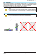
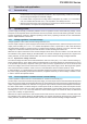
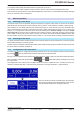
Examples of the type 1 terminal:
• 90° up or down
• space saving in depth
• no bending radius
• horizontal lead
• space saving in height
• large bending radius
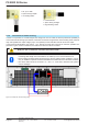
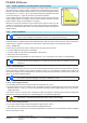
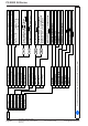
2.3.6 Connection of remote sensing
In order to compensate, to a certain degree, the voltage loss in a DC cable, the device provides the possibility to
connect the remote sensing input “Sense” to the load. The device recognizes the remote sensing mode automati-
cally and regulates the output voltage (only in CV operation) at the load rather than at its own DC output.
Inthetechnicalspecications(seesection „1.9.3. Specic technical data“) the level of maximum possible com-
pensationisgiven.Ifthatisinsufcient,thecablecrosssectionmustbeincreased.
Both pins „NC“ of the Sense connector must not be wired!
• The cross section of the sense cables is noncritical. However, it should be increased with
increasing cable length. Recommendation: for cables up to 5 m use at least 0.5 mm²
• Sense cables should be twisted and laid close to the DC cables to damp oscillation. If neces-
sary, an additional capacitor should be installed at the load/consumer to eliminate oscillation
• The sense cables must be connected + to + and - to - at the load, otherwise both systems
may be damaged
Figure 8 - Example for remote sensing wiring