Elektro-Automatik Operating Guide PS 9000 1U DC Laboratory Power Supply Doc ID: PS91UEN Revision: 02 Date: 04/2015
PS 9000 1U Series TABLE OF CONTENTS 1 GENERAL 1.1 1.1.1 1.1.2 1.1.3 1.1.4 1.2 1.3 1.4 1.5 1.6 1.7 1.7.1 1.7.2 1.7.3 1.7.4 1.7.5 1.8 1.8.1 1.8.2 1.8.3 1.8.4 1.9 1.9.1 1.9.2 1.9.3 1.9.4 1.9.5 1.9.6 1.9.7 1.9.8 1.9.9 2 About this document.......................................5 Retention and use...........................................5 Copyright.........................................................5 Validity.............................................................5 Explanation of symbols........
PS 9000 1U Series 4.3.1 4.3.2 4.4 4.4.1 4.4.2 4.4.3 Update of control panel (HMI)......................49 Update of communication unit (KE).............49 Calibration (readjustment)............................50 Preface..........................................................50 Preparation....................................................50 Calibration procedure...................................50 5 ACCESSORIES AND OPTIONS 6 SERVICE & SUPPORT 5.1 Overview..........................................
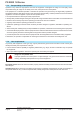
PS 9000 1U Series 1. General 1.1 About this document 1.1.1 Retention and use This document is to be kept in the vicinity of the equipment for future reference and explanation of the operation of the device. This document is to be delivered and kept with the equipment in case of change of location and/or user. 1.1.2 Copyright Reprinting, copying, also partially, usage for other purposes as foreseen of this manual are forbidden and breach may lead to legal process. 1.1.
PS 9000 1U Series 1.4 Disposal of equipment 1.5 Product key A piece of equipment which is intended for disposal must, according to European laws and regulations (ElektroG, WEEE) be returned to the manufacturer for scrapping, unless the person operating the piece of equipment or another, delegated person is conducting the disposal.
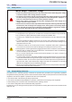
PS 9000 1U Series 1.7 Safety 1.7.1 Safety notices Mortal danger - Hazardous voltage • Electrical equipment operation means that some parts can be under dangerous voltage. Therefore all parts under voltage must be covered! • All work on connections must be carried out under zero voltage (output not connected to load) and may only be performed by qualified and informed persons.
PS 9000 1U Series 1.7.3 Responsibility of the operator Operator is any natural or legal person who uses the equipment or delegates the usage to a third party, and is responsible during its usage for the safety of the user, other personnel or third parties. The equipment is in industrial operation. Therefore the operators are governed by the legal safety regulations.
PS 9000 1U Series 1.7.5 Alarm signals The equipment offers various possibilities for signalling alarm conditions, however, not for danger situations. The signals may be optical (on the display as text) acoustic (piezo buzzer) or electronic (pin/status output of an analog interface). All alarms will cause the device to permanently or temporarily switch off the DC output.
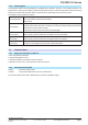
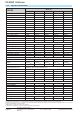
PS 9000 1U Series 1.8.3 Specific technical data Model 1U 1500 W PS 9080-50 PS 9200-25 PS 9360-15 PS 9500-10 PS 9750-06 Input voltage 100...264 V AC 100...264 V AC Input connection 1ph,N,PE 1ph,N,PE 100...264 V AC 100...264 V AC 100...264 V AC 1ph,N,PE 1ph,N,PE 1ph,N,PE Input frequency 50/60 Hz 50/60 Hz 50/60 Hz 50/60 Hz 50/60 Hz Input fuse (internal) Leak current T16 A T16 A T16 A T16 A T16 A < 3.5 mA < 3.5 mA < 3.5 mA < 3.5 mA < 3.5 mA Power factor ~ 0.99 ~ 0.99 ~ 0.
PS 9000 1U Series Model 1U 1500 W PS 9080-50 PS 9200-25 PS 9360-15 PS 9500-10 PS 9750-06 Analog interface (1 Type Sub-D, 15 pole, female Set value inputs U, I, P U, I, P U, I, P U, I, P U, I, P Actual value output Status signals U, I DC on/off, Remote on/off CV, OVP, OT U, I DC on/off, Remote on/off CV, OVP, OT U, I DC on/off, Remote on/off CV, OVP, OT U, I DC on/off, Remote on/off CV, OVP, OT U, I DC on/off, Remote on/off CV, OVP, OT Galvanic isolation to the device Max.
PS 9000 1U Series Model 1U 3000 W PS 9080-100 PS 9200-50 PS 9360-30 PS 9500-20 PS 9750-12 Input voltage 207...264 V AC 207...264 V AC 207...264 V AC 207...264 V AC 207...264 V AC Input connection 1ph,N,PE Input frequency 50/60 Hz 1ph,N,PE 1ph,N,PE 1ph,N,PE 1ph,N,PE 50/60 Hz 50/60 Hz 50/60 Hz 50/60 Hz Input fuse (internal) Leak current T16 A T16 A T16 A T16 A T16 A < 3.5 mA < 3.5 mA < 3.5 mA < 3.5 mA < 3.5 mA Power factor ~ 0.99 ~ 0.99 ~ 0.99 ~ 0.99 ~ 0.
PS 9000 1U Series Model 1U 3000 W PS 9080-100 PS 9200-50 PS 9360-30 PS 9500-20 PS 9750-12 Analog interface (1 Type Sub-D, 15 pole, female Set value inputs U, I, P U, I, P U, I, P U, I, P U, I, P Actual value output Status signals U, I DC on/off, Remote on/off CV, OVP, OT U, I DC on/off, Remote on/off CV, OVP, OT U, I DC on/off, Remote on/off CV, OVP, OT U, I DC on/off, Remote on/off CV, OVP, OT U, I DC on/off, Remote on/off CV, OVP, OT Galvanic isolation to the device Max.
Page 14 EA Elektro-Automatik GmbH Helmholtzstr. 31-33 • 41747 Viersen Germany Fon: +49 2162 / 3785-0 Fax: +49 2162 / 16230 A - Mains switch B - Control panel C - Control interfaces (digital, analog) D - Exhausts E - Share Bus and remote sensing connectors F - DC output G - AC input connector 1.8.4 Figure 2 - Rear side Figure 1 - Front side PS 9000 1U Series Views www.elektroautomatik.de ea1974@elektroautomatik.
Figure 3 - Left hand side view with DC cover Figure 4 - Right hand side view without DC cover PS 9000 1U Series EA Elektro-Automatik GmbH Helmholtzstr. 31-33 • 41747 Viersen Germany Fon: +49 2162 / 3785-0 Fax: +49 2162 / 16230 www.elektroautomatik.de ea1974@elektroautomatik.
PS 9000 1U Series Figure 5 - Top view Page 16 EA Elektro-Automatik GmbH Helmholtzstr. 31-33 • 41747 Viersen Germany Fon: +49 2162 / 3785-0 Fax: +49 2162 / 16230 www.elektroautomatik.de ea1974@elektroautomatik.
PS 9000 1U Series Figure 6 - Control Panel Overview of the elements of the operating panel For a detailed description see section „1.9.4. The control panel (HMI)“. (1) Display Used for indication of set values, menus, conditions, actual values and status. Left hand rotary knob, with pushbutton function (2) Turn: adjusts various set values which are related to the DC output voltage.
PS 9000 1U Series 1.9 Construction and function 1.9.1 General description The electronic high performance power supplies of the PS 9000 1U series are especially suitable for test systems and industrial controls due to their compact construction in a 19” enclosure with 2 height units (2U). For remote control using a PC or PLC the devices are provided as standard with a USB-B slot and an Ethernet port on the back side as well as a galvanically isolated analog interface.
PS 9000 1U Series 1.9.4 The control panel (HMI) The HMI (Human Machine Interface) consists of a display, two rotary knobs with pushbutton function and six pushbuttons. 1.9.4.1 Display The graphic display is divided into a number of areas.
PS 9000 1U Series This area furthermore displays various status texts: Display Description Locked The HMI is locked Remote The device is under remote control from... Analog ...the built-in analog interface USB ...the built-in USB port or a plug in interface module Ethernet ...the built-in Ethernet/LAN port Local 1.9.4.
PS 9000 1U Series 1.9.6 USB port The USB-B port on the back side of the device is provided for communication with the device and for firmware updates. The included USB cable can be used to connect the device to a PC (USB 2.0, USB 3.0). The driver is delivered on the included CD or is available as download and installs a virtual COM port. Details for remote control can be found in external documentation, a general programming guide, on the web site of the manufacturer or on the included CD.
PS 9000 1U Series 2. Installation & commissioning 2.1 Transport and storage 2.1.1 Transport • • • • • 2.1.2 The handles on the front side of the device are not for carrying! Do not transport when switched on or connected! When relocating the equipment use of the original packing is recommended The device should always be carried and mounted horizontally Use suitable safety clothing, especially safety shoes, when carrying the equipment, as due to its weight a fall can have serious consequences.
PS 9000 1U Series 2.3.3 Installing the device • • • • Select the location for the device so that the connection to the load is as short as possible! Leave sufficient space behind the equipment, minimum 30cm, for ventilation! The device is not stackable! Do not put anything with a total weight of more than 1kg on top of the device! A device in a 19” housing will usually be mounted on suitable rails and installed in 19” racks or cabinets. The depth of the device and its weight must be taken into account.
PS 9000 1U Series 2.3.5 Connection to DC loads • In the case of a device with a high nominal current and hence a thick and heavy DC connection cable it is necessary to take account of the weight of the cable and the strain imposed on the DC connection. Especially when mounted in a 19” cabinet or similar, where the cable hangs on the DC output, a strain reliever should be used.
PS 9000 1U Series 2.3.6 Grounding of the DC output Individually operated devices can always be grounded from the DC minus pole, i.e. can be directly connected to PE. The DC plus pole, however, if it is to be grounded, may only be so for output voltages up to 400 V, unless stated otherwise in the technical specifications.
PS 9000 1U Series 2.3.9 Connecting the analog interface The 15 pole connector (Type: Sub-D, D-Sub) on the rear side is an analog interface. To connect this to a controlling hardware (PC, electronic circuit), a standard plug is necessary (not included in the scope of delivery). It is generally advisable to switch the device completely off before connecting or disconnecting this connector, but at least the DC output. The analog interface is galvanically isolated from the device internally.
PS 9000 1U Series 2.3.12 Initial network setup The device is delivered with default network parameters (see „3.4.3.6. Menu “Communication”“). The Ethernet/ LAN port is immediately ready for use after the initial commission. Default parameters: IP: 192.168.0.2 Subnet mask: 255.255.255.0 Gateway: 192.168.0.1 Port: 5025 DHCP: off For wiring, i.e. the hardware connection to a network, contact and ask your IT manager or any similar responsible person. Network cable of common type (CAT5 or better) can be used.
PS 9000 1U Series 3. Operation and application 3.1 Important notes 3.1.
PS 9000 1U Series 3.2.3 Power regulation / constant power / power limiting Power regulation, also known as power limiting or constant power (CP), keeps the DC output power of a power supply constant if the current flowing to the load in relation to the output voltage and the resistance of the load reaches the adjusted power value according to P = U * I resp. P = U² / R. The power limitation then regulates the output current according to I = sqr(P / R), where R is the load’s resistance.
PS 9000 1U Series 3.3 Alarm conditions This section only gives an overview about device alarms. What to do in case your device indicates an alarm condition is described in section „3.6. Alarms and monitoring“. As a basic principle, all alarm conditions are signalled optically (Text + message in the display), acoustically (if activated) and as a readable status via the digital interface. With any alarm occurring, the DC output of the device is switched off.
PS 9000 1U Series 3.4 Manual operation 3.4.1 Switching on the device The device should, as far as possible, always be switched on using the rotary switch on the front of the device. Alternatively this can take place using an external cutout (contactor, circuit breaker) of suitable current capacity. After switching on, the display will show the manufacturers logo for a few seconds, plus some information like device model, firmware version(s), serial number and item number and will then be ready for use.
MENU Page 32 EA Elektro-Automatik GmbH Helmholtzstr. 31-33 • 41747 Viersen Germany P = ____W OPP = ____W U-max = ____V I-max = ____A P-max = ____W OCP = ____A I = ____A Fon: +49 2162 / 3785-0 Fax: +49 2162 / 16230 HMI lock: Lock all | ON/OFF possible HMI Lock Underlined parameters show the default value after delivery or reset. Alarm sound: ON|OFF Alarm Sound View mode: UI | UP Page Setup Key sound: ON|OFF Brightness: 1...
PS 9000 1U Series 3.4.3.1 Menu “General Settings” Element Allow remote control Analog interface range P. Description 1 Selection “NO” means that the device cannot be remotely controlled over any of the digital or analog interfaces. If remote control is not allowed, the status will be shown as “Local” in the status area on the main display. Also see section 1.9.4.
PS 9000 1U Series 3.4.3.6 Menu “Communication” Here settings for the Ethernet port (on rear side of device) are made. The USB port there doesn’t require any settings. When delivered or after a complete reset, the Ethernet port has following default settings assigned: • DHCP: off • IP: 192.168.0.2 • Subnet mask: 255.255.255.0 • Gateway: 192.168.0.1 • Port: 5025 • DNS: 0.0.0.
PS 9000 1U Series 3.4.3.7 Menu “HMI Setup” These settings refer exclusively to the control panel (HMI) and the display. The table lists all available settings for the HMI, no matter in which submenu they can be found. Element Description Language Selection of the display language between “Deutsch” and “English” Brightness The brightness, i.e. background illumination of the display can be adjusted here. Range is 1...10, default is 10.
PS 9000 1U Series 3.4.5 Display modes for actual and set values In general, the display of a PS 9000 1U device shows the actual output voltage and the related set value in the left half of the display and the actual output current and related set value in the right half. In order to have the power set value in direct access, the display mode can be switched. Mode UI Only voltage (U) and current (I) are displayed. This is the default mode.
PS 9000 1U Series 3.4.7 The quick menu The quick menu is an alternative menu for quick access to offline features while the DC output is online. It is accessible with the button and looks like this: Navigation in the menu is also done with arrow buttons / and . You can select the between view mode and the HMI lock, each with three button pushes. 3.4.8 Switching the DC output on or off The DC output of the device can be manually or remotely switched on and off.
PS 9000 1U Series 3.5 Remote control 3.5.1 General Remote control is principally possible via any of the built-in interface ports USB, Ethernet/LAN or analog. Important here is that only the analog or any digital interface can be in control. It means that if, for example, an attempt were to be made to switch to remote control via the digital interface whilst analog remote control is active (pin Remote = LOW) the device would report an error at the digital interface.
PS 9000 1U Series 3.5.4 Remote control via the analog interface (AI) 3.5.4.
PS 9000 1U Series 3.5.4.3 Analog interface specification Pin Name Type* Description 1 VSEL AI Set voltage value 2 CSEL AI Set current value 3 VREF AO Reference voltage 4 DGND POT Ground for all digital signals Default levels 0…10 V or. 0...5 V correspond to 0..100% of UNom 0…10 V or. 0...5 V correspond to 0..
PS 9000 1U Series 3.5.4.5 Simplified diagram of the pins Digital Input (DI) + The internal circuit requires that a switch with low resistance should be used (relay, switch, circuit breaker etc.) in order to send a clean signal to the DGND. 3.5.4.6 V~0.5 12V A quasi open collector, realised as high resistance pull-up against the internal supply. In condition LOW it can carry no load, merely switch, as shown in the diagram with a relay as example. High resistance input (impedance >40 k....
PS 9000 1U Series In case the DC output is already switched on, toggling the pin will switch the DC output off, similar to what it does in analog remote control: DC output is on Pin „REM-SB“ HIGH LOW HIGH LOW + + + + + Parameter Behaviour „REM-SB“ DC output remains on, nothing is locked. It can be switched on normal or off by pushbutton or digital command. inverted inverted normal DC output will be switched off and locked. Later it can be switched on again by toggling the pin.
PS 9000 1U Series 3.6 Alarms and monitoring 3.6.1 Definition of terms Device alarms (see „3.3. Alarm conditions“) are defined as conditions like overvoltage or overtemperature, signalled in any form to the user of the device in order to take notice. Those alarms are always indicated in the front display as readable abbreviated text, as well as status readable via digital interface when controlling or just monitoring remotely and, if activated, emitted as audible signal (buzzer).
PS 9000 1U Series ►►How to configure the device alarms OVP, OCP and OPP 1. Switch off the DC output and push button to call the setup menu. 2. In the menu navigate to “Settings” and push push . Then in the submenu navigate to “Protection” and again. 3. Set the limits for the equipment alarm relevant to your application if the default value of 110% of nominal is unsuitable. 4. Accept the settings with or discard them with .
PS 9000 1U Series 3.8 Loading and saving a user profile The menu “Profiles” serves to select between a default profile and up to 5 user profiles. A profile is a collection of all settings and set values. Upon delivery, or after a reset, all 6 profiles have the same settings and all set values are 0. If the user changes settings or sets target values then these create a work profile which can be saved to one of the 5 user profiles. These profiles or the default one can then be switched.
PS 9000 1U Series 3.9 Other applications 3.9.1 Parallel operation in Share Bus mode Multiple devices of same kind and model can be connected in parallel in order to create a system with higher total current and hence higher power. To achieve that, the units have to be connected with their DC outputs and their Share Bus. The Share Bus will balance the units in their internal voltage regulation and thus current regulation, which will result in a balanced load distribution.
PS 9000 1U Series 3.9.1.5 Alarms and other problem situations Parallel operation, due to the connection of multiple units and their interaction, can cause additional problem situations which do not occur when operating individual units. For such occurrences the following regulations have been defined: • If one or more slave units are switched off on the AC side (power switch, supply undervoltage) and come back later, they’re automatically included again in the system.
PS 9000 1U Series 4. Service and maintenance 4.1 Maintenance / cleaning The device needs no maintenance. Cleaning may be needed for the internal fans, the frequency of cleanse is depending on the ambient conditions. The fans serve to cool the components which are heated by the inherent power loss. Heavily dirt filled fans can lead to insufficient airflow and therefore the DC output would switch off too early due to overheating or possibly lead to defects.
PS 9000 1U Series 4.3 Firmware updates 4.3.1 Update of control panel (HMI) The firmware of the control panel (HMI), if necessary, is updated via the USB port on the rear side. For this a software tool, a so-called “update tool” is needed which is available from the manufacturer (as download from the manufacturer’s website or upon request), together with the firmware update. 4.3.
PS 9000 1U Series 4.4 Calibration (readjustment) 4.4.1 Preface The devices of series PS 9000 1U feature a function to readjust the most important output values when doing a calibration and in case these values have moved out of tolerance. The readjustment is limited to compensate small differences of up to 1% or 2% of the max. value.
PS 9000 1U Series 4.4.3.1 Set values ►►How to calibrate the DC output voltage 1. Connect a multimeter to the DC output. Connect a load and set it to approx. 5% of the nominal current of the power supply as load current, in this example let’s use 4 A. 2. Enter the setup menu with , then push . In the submenu navigate to “Calibration” using the arrow buttons. In the next screen select “Voltage” and then “Output” and confirm with . The power supply will then switch the DC output on. 3.
PS 9000 1U Series 4.4.3.2 Actual values Actual values of output voltage (with and without remote sensing) and output current are calibrated almost the same way as the set values, but here you don’t need to enter anything, just confirm the displayed values. Please proceed the above steps and instead of “Output” select “Display” in the submenus. After the device shows measured values on display, wait at 2s for measured value to settle and then simply confirm with through all steps. , until you are 4.4.3.
EA-Elektro-Automatik GmbH & Co. KG Entwicklung - Produktion - Vertrieb Helmholtzstraße 31-33 41747 Viersen Telefon: 02162 / 37 85-0 Telefax: 02162 / 16 230 ea1974@elektroautomatik.de www.elektroautomatik.