
User Manual


© EA Elektro-Automatik GmbH & Co. KG, DE-41747 Viersen, Helmholtzstr. 31-33, Tel. 02162-3785-0, Fax. 02162-16230
6
Important details
Technical specifications
Unpacking
Check the contents after unpacking for missing parts or acces-
sories and the unit for any apparent mechanical damages and
loose parts inside the unit. In case of a transport damage please
inform the seller immediately. In that case do not take the unit
into operation.
Commissioning
For safety reasons the unit may only be operated at a mains
power connection provided with a safety ground or via an insulat-
ing transformer safety class 2. The air in- and outlets on the back
side may never be obstructed in order to ensure proper cooling.
Mains power voltage selection and fuse replacement
Before putting the unit into operation make sure that the available
mains power voltage and the setting of the input voltage selector
on the back have the same value (115V or 230V). If it is required
to adjust the input selector to the mains power voltage value, an
input fuse with an appropriate voltage value has to be t as well.
The fuse may only be changed or replaced whilst the unit is dis-
connected from the mains power line. The fuse and the respective
values are shown on the back side of the unit.
General
The power supplies of series PS 3000 B and with up to 320 Watts
are transistor-line regulated. They provide a constant output volt-
age and current with low ripple, fast regulation and several ad-
ditional features. A two-stage transformer with automatic change-
over is used to reduce the heat dissipation on the MOS-FET power
stages. The cooling is supported by temperature controlled fans. All
models are equipped with an analog interface for external control
via 0...10 V or the digital USB interface (UTA 12, USB-to-Analog).
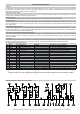
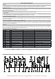
Controls and displays
For an overview see page 12 and following.
Output voltage and current can be preset through coarse and ne
potentiometers placed on the front panel or via 0…10V through the
analog interface. The respective values are shown on the 3-digit
7-segment LED meters or via the analog interface (0…10V).
While pushing the preset key, the preset current and the preset
overvoltage protection value (i.e. OVP, setting through the 10-turn
potentiometer on the front), are displayed on the LED meters.
The regulation mode is indicated via two LEDs.
LED CV = constant voltage mode
LED CC = constant current mode
Furthermore, the LEDs on the front panel show the following
operation conditions.
LED Standby = Shut down by analog interface
LED OVP = Shut down by overvoltage (OVP)
LED OT = Shut down by overheating (OT)
LED External = Analog interface active
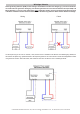
Output terminals
The output is provided through two safety sockets on the front
panel and in addition via screw terminals on the rear side. The
connections for “remote sensing”, i.e. to compensate the voltage
loss on the load wires, are placed on the rear side as well.
Input
Voltage switchable, 115/230V, ±10%
Frequency 50 / 60Hz
Fuse T3.15A at 230V
T6.3A at 115V
Output
Voltage
- Fine adjustment range 0...16V
- Adjustment range approx. 0.8V
- Stability 0...100% load <10mV
- Stability
+
10% U
IN
<1mV
- Ripple <2mV
RMS
- Regulation 10...90% load <1ms
- Regulation 90...10% load <1ms
- Accuracy ±1% of max. value + 2 digits
Current
- Adjustment range 0...10A
- Fine adjustment range approx. 0.5A
- Stability 0...100% U
OUT
<4mA
- Ripple <2mA
RMS
- Accuracy ±1% of max. value + 4 digits
Protection
- Overvoltage protection (OVP) 0...17.6V
- Overtemperature protection (OT) Output shutdown
Control elements
Voltage adjustment Potentiometers coarse/ne
Current adjustment Potentiometers coarse/ne
Overvoltage protection Trimmer 10 turns
Preset OVP / Current Push button (Preset)
Indicators
Voltage LED 7 segment, 3 digits
Current LED 7 segment, 3 digits
Overvoltage protection LED 7 segment, 3 digits
Status indication by LEDs
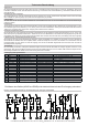
Analog interface
Inputs Signal
Voltage 0...100% 0...10V
Current 0...100% 0...10V
Remote Control On/Off (SEL-enable) open collector
Output On/Off (Standby) open collector
Outputs Signal
Voltage 0...100% 0...10V
Current 0...100% 0...10V
Supply voltage (+VCC) 12...15V 100mA
Reference voltage (VREF) 10.0V 5mA
Overvoltage indicator (OVP) open collector
Overtemperature indicator (OT) open collector
Control mode (CV/CC) open collector
Miscellaneous
Operating temperature 0...40°C
Storage temperature -20...70°C
Relative humidity <80% w/o condensation
Dimensions (WxHxD) 240x120x285mm
Installation dimensions (WxHxD) 240x132x325mm
Protection class 1
Accessories
USB interface UTA12
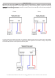
Note:
The DC output is protected against overvoltages by means of sup-
pressor diodes from the DC poles to ground (PE). Thus the potential
of both poles must not be raised higher than 100V above PE. This
also impacts the serial connection of units. Security tests have to
be performed with appropriately low test voltages.