Labornetzgeräte Laboratory Power Supplies PS 2000 B PS 2042-06B: PS 2042-10B: PS 2084-03B: PS 2084-05B: 39 200 112 39 200 113 39 200 116 39 200 117
DE Allgemeines Impressum Elektro-Automatik GmbH & Co. KG Sicherheitshinweise Helmholtzstrasse 31-33 41747 Viersen Germany Telefon: 02162 / 37850 Fax: 02162 / 16230 Web: www.elektroautomatik.de Mail: ea1974@elektroautomatik.de © Elektro-Automatik Nachdruck, Vervielfältigung oder auszugsweise, zweckentfremdete Verwendung dieser Bedienungsanleitung sind verboten und können bei Nichtbeachtung rechtliche Schritte nach sich ziehen.
DE Über das Gerät 1. Einleitung Die Labornetzgeräte der Serie PS 2000B sind sehr kompakte und robuste Geräte, die auf kleinem Raum eine Vielzahl von interessanten Möglichkeiten bieten. Die Geräte eignen sich aufgrund des berührungsfreien Aufbaus und der einfachen Handhabung besonders für den Einsatz in Schule, Ausbildung, Werkstatt oder Labor. Es sind zwei Leistungsklassen mit 100W oder 160W verfügbar.
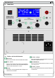
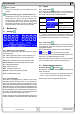
DE Über das Gerät 4. Ansichten Bild 1 Bild 2 4.1 Bedien- und Anschlußelemente Netzschalter Einsteller „Voltage“ Dient zum Einschalten oder Ausschalten des Gerätes. Dient zum Einstellen der Ausgangsspannung oder der Überspannungsschwelle OVP. Taster „Preset“ Mini-USB-Buchse Dient zur Umschaltung der Anzeige auf die Sollwerte. Weiterhin wird mit der Taste die Bedienfeldsperre aktiviert. Siehe Abschnitte 5.4 und 5.5. Dient zum Anschluß des Gerätes an einen PC. Siehe auch Abschnitt 8.3.
DE Über das Gerät 5.2 Tasten Taster „On/Off“ Dient zum Einschalten oder Ausschalten des Ausganges. Leistungsausgang, gepolt, Sicherheitsbuchsen Die Buchsen können zum Einstecken von 4mm Büschelsteckern (offen oder geschlossen) verwendet werden. Die Buchse zwischen den beiden DC-Ausgangsbuchsen ist mit dem Schutzleiter der Netzzuleitung verbunden und kann zur Erdung eines angeschlossenen Verbrauchers genutzt werden. 5. Bedienung 5.2.
DE Bedienung des Gerätes 5.4 Sollwerte einstellen Bei der Einstellung von Strom und Spannung beeinflussen sich die beiden Sollwerte gegenseitig, um die max. Leistung nach Pmax = UIst * IIst nicht zu überschreiten. Das betrifft manuelle Bedienung genauso wie Fernsteuerung.
DE Bedienung des Gerätes 6.3 Überhitzung Sollte ein Übertemperaturfehler (OT) durch Überhitzung auftreten, wird die Ausgangsspannung abgeschaltet und das Statuskürzel „OT“ im Display angezeigt, zusammen mit dem Text „Error“. Der Ausgang schaltet sich nach dem Abkühlen automatisch wieder ein. Soll dies nicht geschehen, kann der Ausgang während der Übertemperaturphase manuell mit der Taste „On/Off“ abgeschaltet werden. 6.
EN General About Elektro-Automatik GmbH & Co. KG Helmholtzstrasse 31-33 41747 Viersen Germany Phone: +49 2162 / 37850 Fax: +49 2162 / 16230 Web: www.elektroautomatik.de Mail: ea1974@elektroautomatik.de © Elektro-Automatik Reprint, duplication or partly, wrong use of this user instruction manual are prohibited and might be followed by legal consequences.
EN About the device 1. Introduction The laboratory power supplies of the series PS 2000B are very compact and rugged devices and incorporate interesting features within small dimensions. The contactless design makes them ideally suited for operation in schools, educational facilities, workshops or laboratories. The series offers two power classes of 100W and 160W.
EN About the device 4. Views Figure 1 Figure 2 4.1 Controls & sockets Power switch This is used to switch the device completely on or off. Pushbutton „Preset“ This button is used to switch the actual values display to set values display. It is also used to activate the control panel lock. Also see sections 5.4 and 5.5. Display This blue LCD presents all information at one glance.
EN Operating the device Pushbutton „On/Off“ Is used to switch the DC output on or off. 5.2.1 Pushbutton Preset This button is used to switch to preset mode and for activation/deactivation of the LOCK mode. Power output, safety sockets, poled Push Display 1x Mode Display of U/I set values 2x Display of OVP/OCP set values Activation/Deactivation of LOCK mode (also see 5.5) Display of U/I actual values The sockets can be used to plug 4mm open or safety Bueschel plugs.
EN Operating the device 5.4 Adjusting set values When adjusting the set values of voltage (U) and current (I), a rule becomes active where both set values adjust each other in order to not exceed the max. power of the device according to Pmax = Uset * Iset.
EN Operating the device 6.3 Overtemperature If the unlikely event of an overtemperature (OT) error occurs by internal overheating, the output voltage is cut off and the status token „OT“ is shown in the display, together with the text „Error“. The output will automatically switch on again after the unit has cooled down. In case this is not wanted, the output can be manually switched off during the overtemperature period. 6.4 Overcurrent The device can react in two different ways to overload resp.
EA-Elektro-Automatik GmbH & Co. KG Entwicklung - Produktion - Vertrieb Helmholtzstraße 31-33 41747 Viersen Germany Telefon: 02162 / 37 85-0 Telefax: 02162 / 16 230 ea1974@elektroautomatik.de www.elektroautomatik.