
Installation Guide

**
4 / 6
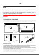
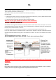
STEP 1. Coupling the drain base outlet to 2″ schedule 40 DWV pipe using correct solvent cement.
STEP 2. Blocking the drain opening with a rag, trowel mortar to build shower pan, reinforce around drain base to be flush with
the floor, grate to create MIN 1% slope towards the drain.
STEP 3. Remove the rag. Lay the waterproof membrane on whole shower pan and cut a slit for the bolts to poke through,
then cut away the waste hole in the center. Bond the membrane around the waste hole with waterproof silicone, the membrane
can be glued directly to the surface of the drain base.
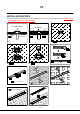
STEP 4. Install the coupling plate and fasten the bolts. Perform a leak test before moving to the next step.
STEP 5. Screw the threaded adapter into the drain base.
STEP 6. Adjusting feet are installed on both sides of drain body, and fasten the screws (as shown in picture 6, and do not
tighten them overly.)
STEP 7. Push the drain outlet into the threaded adapter hole. Spread pea gravel or tile spacer around the drain base to
protect the weep holes.
Adjust drain body by rotating the adjusting feet, the top edge need to be flush with the height of tile surface, then level the
drain body (use a tool, for example, a spirit level).
STEP 8. Trowel mortar onto the membrane, build up the shower floor allowing for thickness of tile and adhesive, grade to
create MIN 1% slope towards the drain.
STEP 9. After the floor mortar has cured, install the floor tile with tile adhesive or thin set mortar, using a notched trowel.
STEP 10. Fill the gap around the drain body with silicone bead or grout, sweep off the excess material.
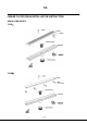
STEP 11. Put the stainless strainer and grate into the drain body successively.
*If your shower drain type is TYPE
Ⅱ
, STEP 11 of installation is as follows.
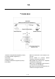
And it has another usage---insert-tile. You can try by the following steps:
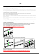
STEP1. Assemble the supporters under the tray (as shown in picture1), ensure it is seated properly. Then turn the opening
frame of the tray upwards for use.
Please pay attention to the installation way of the supporters on both sides of tray in picture 1.
①
②
11
①
②
1
L1=L-0.12 REF.
W1=W-0.12 REF.
2
L
W
3