
User's Manual


September 06, 2022
CLS-4-420-TH
9
||
||
99
16200
Formularized:
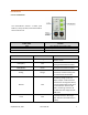
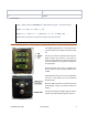
CONNECTIONS
The DROK signal generator is connected to the
screw terminals on the boom of the CLS-4-420-
TH.
Each 6-pin connector represents two channels.
Upper half has Ch.1 and Ch. 2 (as shown in
picture). Lower half has Ch.3 and Ch.4 (As shown
in picture). We are not using 4-pin connector for
this applicaon.
Each channel has 3 pins. Pin 1 is 24 VDC input.
Pin 2 is output current in between 4-20mA. Pin 3
is GND.
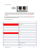
A USB type B connector and a 2.5 mm ID power
jack are on the boom of the CLS-4-420-TH
wireless sensor.
Both the USB connecon and the DC input will
automacally charge the internal lithium-ion
baery.
The DC input accepts a voltage range of 7 VDC to
15 VDC. The power adapter supports upto 2A.
DC Input
Ethernet
USB
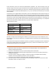
Let T = target interval (in seconds), H = High switch setting, L = Low switch setting
Range 1: If T < 200s: H = 0 and L = T / 20
Range 2: If T >= 200s: H = 1 + T / 2000 and L = (T – (H - 1) x 2000) / 200
(NB: All above operations are based on integers only! (No decimal)