
Assembly Instructions

FEBRUARY 11, 2022
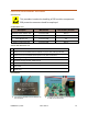
CLS-4-420-th
15
3
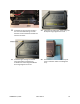
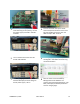
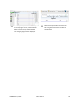
Set the DC power supply to 4.00VDC,
1.3A. Observing correct polarity, connect
the power supply to the BAT+ and BAT-
terminals.
4
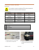
Connect the PACK+ test clip to the DC
acve load posive terminal. Connect the
DC load negave terminal to ether the
GND test clip or BAT- terminal.
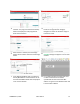
5
Turn on the DC acve load. The Load
should read 0.00 VDC.
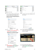
6
Acvate gas gauge by temporarily
shorng BAT+ and PACK+ terminals using
conducve tweezers.
7
Once the gas gauge is acvated, the DC
load should display the same voltage as
the DC power supply ± 10 mV.
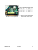
8
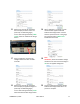
Start the Texas instruments Baery
Management Studio Soware. The
program should automacally detect, read
back, and display the default parameters
stored in the gas gauge.