Instruction Manual Low Profile MagnaValves Electronics Inc. 56790 Magnetic Drive Mishawaka, Indiana 46545 1-800-832-5653 (Toll Free) Phone: 1-574-256-5001 Fax: 1-574-256-5222 E-mail: sales@electronics-inc.com Made in the USA Website: www.electronics-inc.
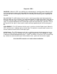
WIRE CONNECTIONS FOR VLP-24 OR LP-24 TO AN AC-24 AMPERAGE CONTROLLER NOTE : The valve must be located as close to the wheel as possible for best servo control stability. ( 5 feet or closer) WHEEL MOTOR Customer CT 100:5 etc. AC-24 Controller 8) Servo Out 9) Valve Enable 19) 24 Vdc Supply 20) 0 Vdc Common VLP-24/LP-24 4) Orange 0-10 Vdc input 6) Blue 24 Vdc Enable 2) Red 24 Vdc Supply 5) Black 0 Vdc Common PANEL METER (IF USED) 0 3 2 4 5 6 1 1. WHITE 2. RED 3. GREEN 4. ORANGE 5. BLACK 6.
Diagnostic LED’s VALVE ON – When this LED is on or blinking, the electromagnet is receiving power. When the LED is off, the permanent magnets will hold or block the shot flow. When the LED is on, but not blinking, the valve flow rate is at full capacity. When the LED is blinking, the electromagnet is regulating the shot flow. Vin > 0.25 Vdc- This LED indicates that the valve is receiving an analog signal input greater than 0.25 Vdc. When this LED is off there is no media flow allowed.
This manual will explain how to replace the mechanical media (grit) valve on a wheel type blast cleaning machine with the new MagnaValve automatic media regulator.
Fig. 2 An air cylinder was used to open and close the original mechanical valve as shown. This air cylinder was controlled by a manually operated 2way air valve. The air cylinder moves the mechanical valve from its closed to open position. The amount of opening was pre-set by the operator by adjusting a nut on the linkage of the air cylinder to limit the stroke. Fig. 2 Fig. 3 This figure shows an ammeter reading of approximately 8 amps, the no-load or no shot flow condition.
Fig. 4 This figure shows the original operating amperage level, in this case approximately 24 amps. Tests indicated a 4 amp error. Fig. 4 Fig. 5 The first step in removing the old mechanical valve is to remove the feed spout going to the wheel inlet. First, remove the four bolts attaching the feed spout to the bottom of the mechanical valve. Caution: Be sure the machine is properly locked out. Follow all safety precautions and instructions shown on the machine or in the owner’s manual. Fig.
Fig. 6 Some machines will have a slide gate or maintenance gate located above the mechanical valve. This should be closed to allow removal of the mechanical valve without draining the shot from the hopper. If the machine does not have a slide gate (this machine did not), you must drain the hopper. Drain the shot from the hopper using a hose or chute to guide the shot into a drum or receptacle. Fig. 6 Fig.
Fig. 8 Once the bolts are removed, remove the valve from the machine. Be careful. The valve is heavy and may contain some shot that may spill upon removal. Fig. 8 Fig. 9 Special adapter plates can be fabricated that will compensate for the bolt hole locations and vertical spacing needed by the MagnaValve. Fig.
Fig. 10 The adapter plates should be installed onto the MagnaValve and the assembly installed as a single unit. The entire MagnaValve assembly can be temporarily positioned and held into place by using vise-grip or similar pliers and then the bolts can be installed and tightened. Note: Adding a nonmetallic 1” spacer above and below the MagnaValve will improve MagnaValve performance. Fig. 10 Fig. 11 The feed spout can now be reinstalled easily, since it bolts directly to the adapter plate.
Fig. 12 The cable fastens to the mating connector. The cable should be routed in either flexible or rigid conduit. In some installations where the conduit for the air cylinder control solenoid is nearby it is possible to reuse the conduit for the MagnaValve cable. Fig. 12 Fig. 13 A new electrical panel was used in this installation and was mounted to a rigid plate prior to performing the wiring.
Fig. 15 Attach the loose current transformer wire to one of the AC-24 controller shunt wires and attach the other AC-24 controller shunt wire to the meter lug. This procedure allows the AC24 controller shunt to be in series with the existing panel meter so that both of them receive the (transformed) motor current (0-5 Amps). If the panel meter is to be eliminated then connect the two current transformer output wires directly to the AC-24 controller shunt. Fig. 15 100.0 Fig.
30.0 Fig. 17 Since this application uses a 30:5 ratio current transformer the AC-24 controller must be adjusted to read 30.0 full scale. Press and hold the Coarse Display Range and Down arrow until 30.0 is displayed. For finer adjustment use the Fine Display Range. Fig. 17 Fig. 18 Start the wheel motor and place a clamp-on type ammeter on the motor leads to confirm calibration of both the panel ammeter and the AC-24 controller display. Note: The AC-24 controller zero and span have been factory set.
The last step of the installation is to adjust the AC-24 controller to the same operating amperage noted before at the beginning of the installation, 24 amps. Push and hold the Setpoint and press the Down arrow until the value 24.0 appears in the display. Release the keypad and notice that the display returns to show the no load amperage.
Fig. 20 Once the final conveyor speed and shot flow rate (motor amps) have been determined, the standard Almen strip (SAE specification J442) can be used to check for proper operation. The Almen strip, shown here, is mounted with four hold-down screws onto a standard Almen holder that has been welded into place on the pipe. This is the industry standard test for the shot peening and blast cleaning intensity. Fig 20 The Almen test strip is blasted on one side only and then removed from the holder.
The advantage of using the Almen strip method lies in the ability to detect the many changes that can occur in a blast machine cleaning operation. Many quality departments are demanding real time process control to satisfy customer requirements for documentation. Instead of relying upon the operator’s judgment of cleanliness, the Almen strip method provides a scientific basis for qualifying the machine. The following are the changes that can be detected by the Almen method: a. b. c. d. e.