
Specifications

20
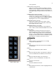
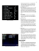
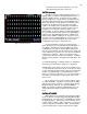
Figure 17 Patch Screen
information from the system and allow you to start
operating the machine with a clean slate.
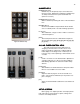
PATCH (screen)
PATCH (screen)PATCH (screen)
PATCH (screen)
To begin you need to understand what a patch is. In a
lighting system you will have many lighting fixtures that you
“plug” into dimmer circuits. You may have several light
fixtures “plugged” into a single dimmer circuit because they
are being used together and do not need individual control.
Often many fixtures on many dimmers are doing the same
thing and you would like to have all of them controlled
together. An example of this would be the many dimmers
that control the auditorium house lights. In many cases it
would be nice to control all of the house lights on one
Channel/fader. To do this, dimmers are Patched (plugged
into) to a Channel/fader via the patch screen. Although the
PATCH screen lists DMR (dimmers) this is a DMX control
address and in addition to dimmers can be used to control
any device that uses USITT DMX512 control protocol for its
operation. This could include items like; color scrollers,
moving lights, fog machines, relay panels, etc.
To get to the PATCH screen you need to push the
[Patch Profile] key once. The PATCH screen will appear on
your display. The Bijou has two patch tables that can be
modified by the user and one default (One-To-One) patch
that can not be modified. The patch allows you to assign one
or more dimmers to a channel. You can also set a maximum
output level for a dimmer. And you can assign a fade in
curve (Profile, see next section) for each dimmer. In addition
dimmers can be ‘Parked’ or changed to Non-Dim units in this
screen.
To select PATCH Page 1 or PATCH Page 2 for modification
use the [F2] key followed by a [1] [Enter] or a [2] [Enter].
NOTE: neither patch will be in use by the board until you go
to setup and make it the “Active Patch”. To do that you would
need to hit [Setup] Default Settings 1 [4] Active Patch [0] One-
To-One or [1] PATCH Page 1 or [2] PATCH Page 2 then
[Enter] to confirm the active patch. If you are just learning the
system leave the default One-To-One patch as the active
patch for now.
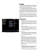
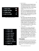
On the Patch screen you will see ninety dimmers listed
at a time, with DMR 1 - 90 shown on the first screen. DMR
(dimmers) are shown as blue #’s. Using the [Page Up] and
[Page Down] keys will let you see up to 1024 dimmers.
NOTE: The number of dimmers and DMX devices in your
system will limit the number of dimmers you will need to
patch.
PATCH AT LEVEL
PATCH AT LEVELPATCH AT LEVEL
PATCH AT LEVEL
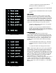
DMR (dimmers) are assigned to CHN (Channels/faders
shown as green #’s) using the [At] [Thru] [And] [Except] [At]
and [Enter] keys. To make CHN 1 control DMR 3 you would
hit; [3] [At] [1] [Enter]. This puts the control of dimmer 3 onto
channel 1 with an output of 100% and Profile 1. As the most
common output level for dimmers is 100%, the LEV (white)
row is left blank unless you input a level other than 100%.