Penta INSTALLATION MANUAL Electronics Line
Table of Contents Introduction ............................................................................................................. 2 Chapter One: Overview .......................................................................................... 3 1.1: Specifications ....................................................................................................3 1.2: Zones ................................................................................................................3 1.
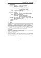
Chapter One: Overview 1.1: Specifications Power Input Power Output Zones Communications Keypads User Codes Operating Temperature Secondary: 15VAC, 22-30VA transformer Battery backup: 12VDC/3.2Ah Auxiliary power: 13.5 - 14.0V (AC operated) 12.0V Nominal (Battery operated) Bell/siren output: 13.5 - 14.0V (AC operated) 12.0V Nominal (Battery operated) 4 (Penta XL) or 8 (Penta Plus XL) Security zones supervised by 2.2K ¼W end of line resistors 1 tamper/ ON/OFF keyswitch zone Accounts: 2 Tel.
Conditional Zone If a perimeter zone with delay is opened first, conditional zones do not generate an alarm when opened during the entry delay. If a conditional zone is opened first, an alarm is generated instantly. Suggested Use: Detectors protecting the area in which a keypad has been installed or the area crossed in order to reach the keypad. Interior Zone Interior zones are automatically bypassed when the system is armed using the ‘Stay’ command 4, 9.
Follow-me The ‘Follow-me’ feature informs the user that events have occurred within their system. When an event occurs, the control panel dials the user’s telephone number and sounds two tones. After hearing the two tones, pressing 3, 6, 9 or # on the telephone sounds additional tones to indicate exactly which type of alarm has occurred. The style of tones indicates the type of alarm generated.
Chapter Two: Installation 2.1: Parts and Options Standard Parts Penta XL or Penta Plus XL household burglary alarm control panel 3104 or 3104 Plus LED keypad 2.
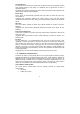
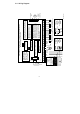
-71 J1 2 LED Keypad AC Transformer 50/60Hz 15VAC 22-30VA Do not connect to a switch controlled receptacle. R B E L D A C K + - 4 AUX + 3 6 KPD K2 K1 5 8 - - + 7 + 2.2K 8 7 10 12 Z2 13 Z3 14 16 17 18 19 20 21 22 1 2 3 4 5 J4 Typical End of Line Resistor N.C. N.C. Zone Connections 2.2K 2.
2.3: Terminal Connections 15-16.5VAC Input (J1) Terminals 1 & 2: Connect a 15VAC transformer rated at 22-30VA, using 18 AWG wire. Auxiliary Power Output (J1) Terminals 3(+), 4(-): The auxiliary power output connections supply power to keypads and peripheral units such as detectors and other powered sensors. Keypad Data Bus Connections (J1) Terminals 5 & 6: Connect up to three LED keypads to terminals 5 (K2), and 6 (K1).
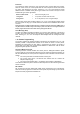
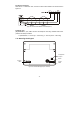
Fire Zone Connections When Zone 1 is defined as Fire, connect four-wire smoke detectors as shown below in Figure 2.4. +12V 7 8 9 10 11 12 Figure 2.4: Four-wire Smoke Detector Connections (Zone 1) Telephone Line (J4) Terminals 1, 2, 3, 4 & 5: Connect the telephone line using standard Telco wires (minimum 26 AWG) as follows: 1 - Optional Earth, 2 - Home Tip, 3 - Home Ring, 4 - Telco Tip and 5 - Telco Ring 2.
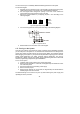
You can connect up to 3 individually addressed LED keypads to the control panel. To mount the keypad: 1. 2. 3. Separate the front and back cover of the keypad by pressing the locking tabs, situated at the bottom of the keypad, with a small flathead screwdriver. Pull the keypad wires through the opening in the back cover nearest the terminal block and mount the back cover to the wall. Define the keypad address by configuring jumpers A & B according to the following diagram.
Chapter Three: System Operation 3.1: General Using any one of the three LED keypads that can be installed with the system, you can perform all operation and programming functions. This section offers a complete explanation of the keypad functions and of the LED display, incorporating a summary of command codes used in system operation. 3.2: Keypad Layout The following diagram shows the keypad layout for the 3104 Plus keypad for use with the Penta Plus XL control panel.
ARMED: The Armed LED lights to indicate the system is armed or in programming mode and flashes during the exit delay. POWER: The Power LED lights up when both AC & battery power are OK, flashes when the battery is low & AC power is OK, and goes out in the event of AC failure. 3.3: Command Codes To execute a command, press the ‘4‘ button followed by the corresponding command number. In certain cases, you are required to enter a valid user code.
Stay Arming This feature only arms perimeter zones – i.e. Perimeter, Perimeter with Delay and Fast Loop Perimeter zones. This allows the user to stay within the protected area while the system is armed. To “Stay” arm the system: 1. Check that all perimeter zones are closed; the Ready LED lights up to indicate that the system is ready to be armed. 2. Press 4, 9. 3. Enter a valid user code; the keypad beeps until the end of the exit delay.
3.6: User Codes The control panel supports four user codes, a duress code and an installer code. Each of these codes are four digits long. Of the four user codes, only User Code 1 (default 1111) has authorization to modify other user codes and the duress code. The installer’s code (default 1234) is the only user code which grants access to the programming parameters and is programmable at address 83. To program user codes 1-4: 1. Press 4, 5. 2.
3.7: Zone Bypassing/Unbypassing A bypassed zone is ignored by the system and will not generate an alarm when tripped. To bypass a zone: 1. Press 4, 1. 2. Enter a valid user code; the System LED flashes and the LEDs of any currently bypassed zones light up. 3. Enter the number of the zone to be bypassed; the corresponding zone LED is lit. 4. Press # to exit bypass mode; the bypassed zones flash. To unbypass a zone: 1. Press 4, 1. 2.
3.9: Additional Operations Bell Cancel To cancel the bell: • Enter a valid user code or turn the keyswitch as if disarming the system. Bell/LED Test To perform a bell/LED test: • Press 4, 4, 1; the siren is sounded and all LEDs on the keypad are lit for a period of two seconds. Walk Test Walk test mode enables you to test peripheral detection devices, such as PIR detectors and magnetic door contacts. In this mode, when a zone is opened or closed, the keypad chimes. To perform a walk test: 1. Press 4, 4, 2.
Chapter Four: Programming 4.1: General The Penta XL series of control panels may be programmed using either the LED keypad or from a PC using the Remote Programmer (RP) software. If using the Remote Programmer, refer to the instructions provided with the software. 4.2: Guide to Programming The control panel has 83 parameter addresses allowing precise custom configuration of the system to the needs of each installation. The options for each address are listed in section 4.3: Programming Parameters.
4.3: Programming Parameters The following section lists the programming parameters which are used to configure the system. For a listing of the default parameters please contact your local dealer. Address 00: Communication Attempts The control panel’s attempts to communicate with the central station are organized in rounds. A communication round is a set of dialing attempts.
Address 02: Communication Options This address consists of the various options used in communication and/or remote programming. Enter five digits according to the following.
Address 07: Zone 5 Definition* Address 08: Zone 6 Definition* Address 09: Zone 7 Definition* Address 10: Zone 8 Definition* Address 11: Entry Delay Time The entry delay timer determines the amount of time the user has to disarm the system before an alarm is activated. The entry delay is only initiated if the premises are entered through a zone defined as ‘perimeter with delay’. Enter a hexadecimal value between 1 and 255 seconds at this address using the hexadecimal conversion chart in Appendix A.
Event Codes All events can be programmed to transmit a two digit event code message to the central station. These codes are usually assigned by the central station - consult the central station operator/owner for a listing of the different event codes. To disable an event code program the code as 00.
Address 46: System Disarmed (User Code 4) Address 47: System Disarmed (Duress Code) Address 48: Low Battery Address 49: AC Loss Address 50: Bell Trouble** Address 51: Keypad Trouble Address 52: Low Battery Restore Address 53: AC Loss Restore ** Address 54: Bell Trouble Restore Address 55: Keypad Trouble Restore Address 56: Bell Cancel Address 57: Periodic Test Address 58: Bypass Zone 1 Address 59: Bypass Zone 2 Address 60: Bypass Zone 3 Address 61: Bypass Zone 4 Address 62: Bypass Zone 5* Address 63: Bypa
Address 74: Primary Communication Protocol Address 75: Duplicate Communication Protocol Address 76: Backup Communication Protocol Telephone numbers Address 77: Primary Telephone Number The Primary 1 telephone number is the first number that is dialed when an event occurs. You can enter a maximum of 16 digits at this address. To add a two-second pause, enter B (4, 1). To switch from pulse to DTMF dialing enter E (4, 4). To add a “4", enter (4, 4). To add a “#”, enter (4, #).
4.4: Periodic Test Timer Reset The control panel sends the periodic test event code (address 57) to the central station once every 24 hours. The first transmission of this code is sent 12 hours after power is applied to the control panel. If a different time is required, you can program the control panel to send the first periodic test message 24 hours after the periodic test timer is reset. To reset the periodic test timer: 1. Press 4, 7 to enter programming mode. 2.
Appendix A: Hexadecimal Conversion Chart The following is a decimal to hexadecimal conversion chart to be used as an aid in programming: Dec Hex Dec Hex Dec Hex Dec Hex Dec Hex Dec Hex Dec Hex Dec Hex 00 00 32 20 64 40 96 60 128 80 160 A0 192 C0 224 E0 01 01 33 21 65 41 97 61 129 81 161 A1 193 C1 225 E1 02 02 34 22 66 42 98 62 130 82 162 A2 194 C2 226 E2 03 03 35 23 67 43 99 63 131 83 163 A3 195 C3 227 E3 04 04 36 24 68 44
Appendix B: Glossary of Terms 24hr Zone A zone which is always active regardless of whether the system is armed or disarmed. Opening a 24hr zone always generates an alarm. AC Loss The disruption of AC power. In the event of AC loss, the panel waits five minutes before sending an event message. Answering Machine Override The method used in RP communication allowing the control panel to share a telephone line with answering machines, fax machines etc.
E Entry Delay See Delay Event Code The two-digit code transmitted to the central station to indicate that an event has occurred. Event Log The two event logs record and display events the system has undergone since the last arming. Exit Delay See Delay Fire Zone A dedicated zone type for verified fire applications. Tripping this zone generates an audible alarm with a distinctive bell pattern.
Primary Telephone Number The first telephone number dialed when an event occurs. Q Quick Arming Arming the system without the need for a valid user code. R Ready The state in which all zones are closed and the system is ready to be armed. Remote Programmer The software used for programming the system using a PC from a remote location or on-site. Restore The restoral of a trouble condition to its normal state.
Index 24hr Zone .................................... 4, 19 Account Number.............................. 23 Additional Operations ...................... 16 Answering Machine Override............. 5 Arming ............................................. 12 F Key................................................13 Fast Loop Perimeter Zone ...........4, 19 Fire Key............................................13 Fire Zone..................................4, 9, 19 Follow-me .........................................
Power LED ...................................... 12 Power Output..................................... 3 Primary Telephone Number............. 23 Programmable Output ..................... 20 Programming................................... 17 Telephone Numbers.....................4, 23 Telephone Options...........................19 Terminal Connections ....................... 8 Test Bell....................................................... 16 Walk.....................................................
Penta XL Series - Default Values COMMUNICATION ATTEMPTS 1 2 (1 communication rounds, 2 dialing attempts in each round ) (00) __,__ (01) SYSTEM PARAMETERS 1 0 1 1 1 ____,____,____,____,____ Keypads One Keypad Keyswitch Function Latching Tamper Zone Definition Tamper Zone E Key Alarm Silent Alarm P Key Alarm Silent Alarm (02) COMMUNICATION PARAMETERS 1 0 1 0 1 ____,____,____,____,____ RP Ring Detection Enabled RP Access Type Passcode RP Access Enable RP Access Handshake 1400Hz Handshake Dialing DTMF ZON
Penta XL Series - Programming Worksheet (00) COMMUNICATION ATTEMPTS ____,____ Communication Rounds 0-F (F=15 rounds) Dialing Attempts 0-F 0 = Disable communications (01) SYSTEM PARAMETERS First Digit: Keypads 0 - No Keypads 1 - One Keypad 2 - Two Keypads 3 - Three Keypads ____,____,____,____,____ Second Digit: Keyswitch Function 0 - Latching 1 - Momentary Third Digit: Tamper Zone Definition 0 - Arm/Disarm Keyswitch 1 - Tamper Zone Fourth Digit: E Key Alarm 0 - Audible 1 - Silent Fifth Digit: P Key Al
EVENT CODES (15) __,__ Alarm from Zone 1 (45) __,__ Disarmed (User 3) (16) __,__ Alarm from Zone 2 (46) __,__ Disarmed (User 4) (17) __,__ Alarm from Zone 3 (47) __,__ Disarmed (Duress) (18) __,__ Alarm from Zone 4 (48) __,__ Low Battery (19) __,__ Alarm from Zone 5* (49) __,__ AC Loss (20) __,__ Alarm from Zone 6* (50) __,__ Bell Trouble† (21) __,__ Alarm from Zone 7* (51) __,__ Keypad Trouble (22) __,__ Alarm from Zone 8* (52) __,__ Low Battery Restore (23) __,__ Tamper Alarm (53) __,__ A