
Operation and programming manual


9
+
3
7
4
8
5
9
6
LOAD
(100mA max.)
AUX
PGM
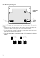
2.4: Terminal Connections
15-16.5Vac Input
Terminals 1 & 2: Connect a 15-16.5Vac transformer rated at 22-30VA, using 18 AWG
wire.
Auxiliary Power Output
Terminals 3(+), 4(-): The auxiliary power output connections supply power to keypads
and peripheral units such as detectors and other powered sensors.
Keypad Data Bus Connections
Terminals 5 & 6: Connect up to three individually addressed LED keypads to terminals
5 (K2), and 6 (K1). Make sure that the wires are connected to the same connections on
the keypad, see 2.5: Mounting the Keypad.
Bell Power Output
Terminals 7(+), 8(-): Connect these terminals to supply power to the bell. The bell
power output supplies AUX power, rated at 600mA max.
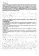
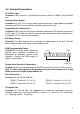
PGM Programmable Output
Terminal 9: The PGM output switches to
ground when activated, enabling the
connection of additional system status
indicators. Connect the PGM output as
shown in the diagram.
Tamper Zone/Keyswitch Connections
Terminal 10: Connect a tamper switch or ON/OFF keyswitch to terminals 10(+) and 12(-).
Note: If neither the tamper zone nor keyswitch are used, short terminal 10 to 12 and
define this zone as Tamper Zone at Address 01.
Zone Connections
Terminals 11, 12, 13, 14, 15 & 16:
ZONE 1: Terminals 11(+) & 12(-) ZONE 3: Terminals 14(+) & 15(-)
ZONE 2: Terminals 13(+) & 12(-) ZONE 4: Terminals 16(+) & 15(-)
Telephone Line
Terminals 17, 18, 19, 20: The telephone line should be connected (using the
standard Telco wires - minimum 26 AWG) as follows: 17 - Home Tip, 18 - Home Ring,
19 - Telco Tip, and 20 - Telco Ring.