
Operation and programming manual


7
CHAPTER TWO: INSTALLATION
2.1: Parts and Options
Penta Household Burglary Alarm Control Panel 1
LED Keypad 1
2.2KΩ ¼W resistors
5
6 x ¼ mounting screws 4
Mounting studs 4
PCB support 1
Installation, Operation, and Programming Manual 1
User Manual 1
Optional Parts List
Additional Penta LED Keypad
‘Remote Programmer’ Up/Downloading Software
12Vdc Adapter for Remote Programmer
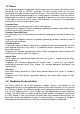
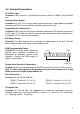
2.2: Fuse Replacement
The layout of the three protection fuses is as follows
F1: The Battery protection fuse protects the battery
charger circuit. To replace this fuse use a 1.6A/250V
fuse.
F2: The AC protection fuse protects terminals 1 and 2.
To replace this fuse use a 1.6A/250V fuse.
F3: The AUX protection fuse protects the auxiliary power
output to the keypad (terminals 3 and 4). To replace
this fuse use a 1.0A/250V fuse.
F4: The Bell Power protection fuse protects the active
bell output (terminals 7 and 8). To replace this fuse
use a 1.0A/250V fuse.
F2 F3F1 F4