Penta Installation, Operation and Programming Electronics Line (E.L.) Ltd. www.elecline.
TABLE OF CONTENTS Introduction......................................................................................................... 4 About the Penta Installation, Operation and Programming Manual ..........................4 Publication Information .............................................................................................4 Chapter One: Overview ...................................................................................... 4 1.1: Specifications .................................
INTRODUCTION About the Penta Installation, Operation and Programming Manual This manual is designed to help you with the installation process for the Penta control panel. We strongly urge you to read through this manual, in its entirety, before beginning the installation process so that you can best understand all that this security system has to offer your customers. This manual is not intended for end user use. End users are encouraged to read the manual accompanying the system, the Penta User Manual.
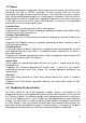
1.2: Zones The Penta control panel includes four security zones plus one tamper zone which can be defined for use with an ON/OFF keyswitch. The four security zones are fully programmable and supervised by end of line resistors. The Penta offers five zone response types for customized programming to suit a wide range of installations. Each zone can be programmed to activate a siren/bell when tripped or to generate a silent alarm where only a message is sent to the central station.
Central Station Communication The Penta uses a standard 20pps 4/2 no parity protocol for central station communication. All events can be programmed to transmit a two digit event code message to the central station. These codes are usually assigned by the central station consult the central station operator for a listing of the different event codes. Follow-me The ‘Follow-me’ feature informs the user that an event has occurred by dialing the user’s telephone number and sounding two beeps.
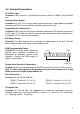
CHAPTER TWO: INSTALLATION 2.1: Parts and Options Penta Household Burglary Alarm Control Panel LED Keypad 2.2KΩ ¼W resistors 6 x ¼ mounting screws Mounting studs PCB support Installation, Operation, and Programming Manual User Manual 1 1 5 4 4 1 1 1 Optional Parts List Additional Penta LED Keypad ‘Remote Programmer’ Up/Downloading Software 12Vdc Adapter for Remote Programmer 2.
2.3: Wiring Diagram + - R E D B L A C K Electronics Line (E.L.) Ltd. - Penta 12V/3.2Ah BATTERY: Replace the battery every 3 - 5 years. The maximum charging current is 350mA. Household Burglary Alarm Panel JPD Jumper for factory default restore Electronics Line (E.L.) recommends testing the system at least once a week. Refer to the testing procedure found in the user manual. PROTECTION FUSES: F1 (BATT): 1.6A/250V F2 (AC): 1.6A/250V F3 (AUX): 1.0A/250V F4 (Bell): 1.
2.4: Terminal Connections 15-16.5Vac Input Terminals 1 & 2: Connect a 15-16.5Vac transformer rated at 22-30VA, using 18 AWG wire. Auxiliary Power Output Terminals 3(+), 4(-): The auxiliary power output connections supply power to keypads and peripheral units such as detectors and other powered sensors. Keypad Data Bus Connections Terminals 5 & 6: Connect up to three individually addressed LED keypads to terminals 5 (K2), and 6 (K1).
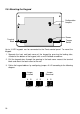
2.5: Mounting the Keypad Configuration Jumpers Buzzer Terminal Block Tamper Switch Up to 3 LED keypads can be connected to the Penta control panel. To mount the keypad: 1. Separate the front and back cover of the keypad by pressing the locking tabs, situated at the bottom of the keypad, with a small flathead screwdriver. 2. Pull the keypad wires through the opening in the back cover nearest the terminal block and mount the back cover to the wall. 3.
4. Connect the keypad to the control panel according to the following diagram. + 3 K2 K1 5 6 4 CONTROL PANEL KEYPAD K1 K2 + 5. Reassemble the front and back cover of the keypad. 2.6: Turning on the System Once all of the systems components are properly connected to their destination terminals, the Penta is ready to be turned on.
CHAPTER THREE: SYSTEM OPERATION 3.1: General All operation and programming of the Penta can be performed using any one of the three LED keypads that can be installed with each system. This section offers a complete explanation of the keypad functions and of the LED display, incorporating a summary of command codes used in system operation. 3.
3.3: Command Codes Commands are executed by pressing the ‘Q‘ button followed by the corresponding command number and, in some cases, a valid user code. The following is a summary of the command codes used in system operation.
Stay Arming This feature only arms perimeter zones. This allows the user to stay within the protected area while the system is armed. To “Stay” arm the system: 1. Check that all zones are closed apart from the interior zones; the Ready LED lights up to indicate that the system is ready to be armed. 2. Press Q, 9. 3. Enter a valid user code; the keypad beeps until the end of the exit delay. Immediate Arming The system can be operated without an entry/exit delay.
3.7: User Codes The Penta is capable of maintaining four user codes, a duress code and an installer code. Each of these codes are four digits long. Of the four user codes, only User Code 1 (default 1111) has authorization to modify other user codes and the duress code. The installer’s code (default 1234) is the only user code which grants access to the programming parameters and is programmable at address 61. To program user codes 1-4: 1. Press Q, 5. 2.
3.8: Zone Bypassing/Unbypassing The Penta offers the user the ability to bypass zones. When a zone is bypassed, it is ignored by the system and will not generate an alarm when tripped. To bypass a zone: 1. Press Q, 1. 2. Enter a valid user code; the System LED flashes and the LEDs of any currently bypassed zones light up. 3. Enter the number of the zone to be bypassed; the corresponding zone LED lights up. 4. Press # to exit bypass mode; the bypassed zones flash. To unbypass a zone: 1. Press Q, 1. 2.
3.10: Additional Operations Bell Cancel To cancel the bell: • Enter a valid user code or turn the keyswitch as if disarming the system. Bell/LED Test To perform a bell/LED test: • Press Q, 4; the siren is sounded and all LEDs on the keypad are lit for a period of two seconds. Zone Chime On/Off The keypad can be set to chime when Perimeter With Delay or Perimeter zones are opened or closed. This feature only functions when the system is disarmed.
CHAPTER FOUR: PROGRAMMING 4.1: General The Penta control panel may be programmed using either the LED keypad or Electronics Line’s Remote Programmer. If using the Remote Programmer, refer to the instructions provided with the software. 4.2: Guide to Programming The control panel has 61 parameter addresses allowing precise custom configuration of the system to suit the user’s needs. The options for each address are listed in section 4.3: Programming Parameters.
4.3: Programming Parameters The following section lists the Penta’s programming parameters which are used to configure the system. For a listing of the default parameters please contact your local dealer. Address 01: Miscellaneous This address offers a number of options regarding the system set-up.
Address 03: Zone 1 Definition One of five response types can be assigned to zone 1. Each zone type can be programmed as ‘Silent’ or ‘Audible’. A ‘Silent’ zone will not activate a siren or bell when the zone is tripped.
Address 10: PGM Options The PGM (Programmable Output) can be used for indication of certain status or trouble conditions. When the PGM output is activated terminal 9 switches to ground. Choose the PGM output setting from the following table.
Address 26: [E] Key alarm restore Address 27: System Armed (User Code 1) Address 28: System Armed (User Code 2) Address 29: System Armed (User Code 3) Address 30: System Armed (User Code 4) Address 31: System Disarmed (User Code 1) Address 32: System Disarmed (User Code 2) Address 33: System Disarmed (User Code 3) Address 34: System Disarmed (User Code 4) Address 35: System Disarmed (Duress Code) Address 36: Low Battery Address 37: AC Loss Address 38: Not In Use Address 39: Keypad Trouble Address 40: Low Ba
Telephone numbers Address 54: Primary Telephone Number The primary telephone number is the first number that is dialed when an event occurs. A maximum of 16 digits can be entered at this address. To add a two-second pause, enter B (Q, 1). To switch from pulse to DTMF dialing enter E (Q, 4). These hexadecimal digits, B and E, are included in the 16 digit total. Press ENTER after the last digit of the telephone number has been programmed.
APPENDIX A: HEXADECIMAL CONVERSION CHART The following is a decimal to hexadecimal conversion chart to be used as an aid in programming: Dec Hex Dec Hex Dec Hex Dec Hex Dec Hex Dec Hex Dec Hex Dec Hex 00 00 32 20 64 40 96 60 128 80 160 A0 192 C0 224 E0 01 01 33 21 65 41 97 61 129 81 161 A1 193 C1 225 E1 02 02 34 22 66 42 98 62 130 82 162 A2 194 C2 226 E2 03 03 35 23 67 43 99 63 131 83 163 A3 195 C3 227 E3 04 04 36 24 68 44
APPENDIX B: GLOSSARY OF TERMS 24hr Zone A zone which is always active regardless of whether the system is armed or disarmed. Opening a 24hr zone always generates an alarm. A AC Loss The disruption of AC power. In the event of AC loss, the panel waits five minutes before sending an event message.0 Answering Machine Override The method used in RP communication allowing the control panel to share a telephone line with answering machines, fax machines etc.
Distress Keys The three distress keys (F, E and P) generate different types of alarm when pressed and held down for two seconds. Duress Code Entering the duress code generates a silent alarm to indicate that the user is being forced to disarm the system or cancel the bell. E Entry Delay See Delay Event Code The two-digit code transmitted to the central station to indicate that an event has occurred.
P Perimeter Zone Perimeter zones are armed during both regular and Stay arming and can be defined with or without an exit delay. Periodic Test The periodic test event code is sent to the central station every 24 hours to indicate that the system is functional. PGM Output Primary Telephone Number Programmable output for connecting additional system status indicators. The first telephone number dialed when an event occurs.
INDEX 24hr zone ........................................20 24hr Zone ..........................................5 AC Protection Fuse............................7 Account Number ..............................23 Additional Operations ......................17 Answering Machine Override..............6 Armed LED......................................12 Arming.............................................13 Forced .....................................................13 Immediate .....................................
Parameter Addresses ......................18 Parameters programming............................................19 Parts List of.........................................................7 Optional .....................................................7 Perimeter Zone ...................... 5, 17, 20 Perimeter Zone With Delay ..........5, 20 Periodic Test Timer Reset................23 PGM................................................21 Police Key .......................................14 Power Input .......
ELECTRONICS LINE (E. L.) LTD. AND ITS SUBSIDIARIES - LIMITED WARRANTY ELECTRONICS LINE (E. L.) LTD. AND ITS SUBSIDIARIES (EL) warrants its products to be free from manufacturing defects in materials and workmanship for two years following the date of sale. EL will, within said period, at its option, repair or replace any product failing to operate correctly without charge to the original purchaser or user. In case of defect, contact the security professional who installed and maintains your security system.
Penta - Programming Worksheet (01) SYSTEM PARAMETERS P and E Key Function P and E Audible Alarms - 0 E Audible Alarm, P Silent Alarm - 1 E Silent Alarm, P Audible Alarm - 2 P and E Silent Alarms - 3 0 ____,____,____,____,____ Keyswitch Function Latching - 0 Momentary - 8 Tamper Zone Definition Arm/Disarm Switch - 0 Tamper Zone- 4 Keypads No Keypads - 0 One Keypad - 1 Two Keypads - 2 Three Keypads - 3 (02) COMMUNICATION PARAMETERS Dialing Pulse - 0 DTMF - 1 ____,____,____,____,____ RP Access Type Access
EVENT CODES (11) __,__ Alarm from Zone 1 (32) __,__ Disarmed (User 2) (12) __,__ Alarm from Zone 2 (33) __,__ Disarmed (User 3) (13) __,__ Alarm from Zone 3 (34) __,__ Disarmed (User 4) (14) __,__ Alarm from Zone 4 (35) __,__ Disarmed (Duress) (15) __,__ Tamper Alarm (36) __,__ Low Battery (16) __,__ [P] Key Alarm (37) __,__ AC Loss (17) __,__ [F] Key Alarm (39) __,__ Kpd Trouble (18) __,__ [E] Key Alarm (40) __,__ Low Battery Restore (19) __,__ Zone 1 Restore (41) __,__ AC Loss Restore (2
Penta – Default Values (01) SYSTEM PARAMETERS 3 0 0 4 1 ____,____,____,____,____ P and E Key Function P and E Silent Alarms Keyswitch Function Latching Tamper Zone Definition Tamper Zone Keypads One Keypad (02) COMMUNICATION PARAMETERS 1 0 4 0 0 ____,____,____,____,____ Dialing DTMF RP Access Type Access Code RP Access Enable RP Access Handshake 1400Hz Handshake Protocol 20 pps 4/2 No Parity ZONE DEFINITIONS (03 - 06) Default value for all zones: 00 – Perimeter zone with delay (silent) TIMERS 0 F h Entry