
Installation guide


4
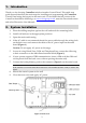
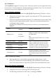
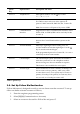
Figure 2: Power Supply and Connections Board
1. AC Power Connector
(N=Neutral, L=Live)
2. AC Fuse
3. Terminal Block
4. Back Tamper Connector
5. AC to AC Transformer
6. Front Tamper Switch
7. Flat-Cable Interface Connector to
the Main Board
8. Battery Connector
9. PGM Control Jumper (JP1)
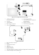
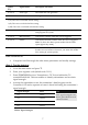
Figure 3: Main board
1. Built-in Sounder Connector
2. Buzzer
3. LCD Contrast Control
4. USB Port
5. SIM-Card Holder
6. Speaker Connector
7. Flat-Cable Interface Connector to the Power Supply and Connections Board
8. Sounder Strength Control Jumper (JP1)