
User's Manual

Operation and Adjustment
Warm-Up Time: The detector will need to warm up for the first 90 seconds after applying power.
Setting the pulse counter: The pulse counter determines the amount of
beams that need to be crossed before the detector will produce an alarm.
The available options are 1, 2 or Adaptive pulse count. Using the
Adaptive pulse count feature, the detector chooses between 1 or 2 pulses
based on its analysis of the received signal. To set the pulse counter,
refer to Table 1 for the appropriate DIP-switch setting.
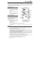
Vertical Adjustment: To position the PCB, turn the Easy Lock counter-clockwise and slide the PCB up or down to
the required setting using the vertical adjustment scale. The sensor’s coverage area is 40’ x 40’ (12m x 12m) when
the PCB is positioned at -4. This is also the setting for maximum pet immunity. Slide the PCB up towards the -8
position to decrease the coverage area bringing the beams closer to the mounting wall.
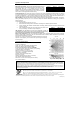
Walk Test Mode: A walk test is performed in order to determine the lens coverage pattern of the detector– see Figure 2.
Placing the Mode jumper over pins 1 & 2 cancels the delay time between detections, enabling you to perform an
efficient walk test.
To walk test the sensor:
1. Place the Mode jumper over pins 1 & 2.
2. Walk across the coverage area of the detector according to the detection pattern selected.
3. Confirm that the LED activates and deactivates accordingly. Wait five seconds after each detection before
continuing the test.
4. After completing the walk test, remove the jumper and place it over
one pin for storage - see Mode Jumper Safeguard.
LED indication: The LED indicator is lit every time a transmission is made. To
enable/disable LED indication, refer to Table 2 for the appropriate DIP-switch setting.
Note: The LED should only be disabled after successfully walk testing the detector.
Mode Jumper Safeguard: During normal operation, the Mode jumper should be placed over one pin for storage.
When the mode jumper is placed over two pins, the detector is either in Radio or Walk Test Mode. As a precaution,
these modes are limited to four minutes.
After the four minutes have expired, the detector switches back to normal
operation. If this happens, you can reset a mode by removing and replacing
the mode jumper.
Technical Specifications
Antenna: Built-in Internal Whip
Frequency: 418MHz FM
Power: 3.6V ½ AA Lithium Battery
(Part No. BT5055)
Caution: Fire, explosion and severe burn hazard!
Do not recharge, disassemble or heat above 212°F (100°C).
Current Consumption: 30mA (transmission), 6µA (standby)
Pyroelectric Sensor: Dual Element
Maximum Coverage: 40’ x 40’ (12 x 12m)
Pulse Count: 1, 2 or Adaptive (selectable)
LED Indicator: Selectable
Adaptive Temperature Compensation
RFI Immunity: 30V/m
Operating Temperature:14 to 140°F (-10 to 60°C)
Fire Protection: ABS Plastic Housing
Dimensions: 4.3”H X 2.4”W X 1.8”D (110 x 60 x 45mm)
FCC ID: RIYEL2645-PI
Side View
Top View
Switch 1 Switch 2 Pulse Count
OFF OFF 1
OFF ON 2
ON ON Adaptive
Table 1
Figure 2: Lens Coverage Diagram
Switch 3 LED Indicator
OFF Disabled
ON Enabled
Table 2
Electronics Line 3000 Ltd.: 2 Granit Street, Kiryat Arieh, POB 3253, Petah Tikvah 49130 Israel. Tel: (972-3) 918-1333, Fax: (972-3) 922-0831
USA: 5637 Arapahoe Avenue, Boulder, Colorado 80303. Tel: (800) 683-6835, Fax: (303) 938-8062
UK: Unit 7, Leviss Trading Estate, Station Road, Stechford, Birmingham B33 9AE. Tel: (44-121) 789-8111, Fax: (44-121) 789-8055
France: ZI-61, rue du Marché Rollay, 94500 Champigny-Sur-Marne. Tel: (33-1) 45.16.19.20, Fax: (33-1) 45.16.19.29
ZI0323A (11/03)
A
ll data is subject to change without prior notice. In no event shall Electronics Line 3000 Ltd. (EL3K) be liable for an amount in excess of EL3K.’s original selling price o
f
this product, for any loss or damage whether direct, indirect, incidental, consequential or otherwise arising out of any failure of the product.
Note: This equipment has been tested and found to comply with the limits for a Class B digital device, pursuant to part 15 of the FCC Rules. These limits are
designed to provide reasonable protection against harmful interference in a residential installation. This equipment generates, uses and can radiate radio frequenc
y
energy and, if not installed and used in accordance with the instructions, may cause harmful interference to radio communications. However, there is no guarantee
that interference will not occur in a particular installation. If this equipment does cause harmful interference to radio or television reception, which can be determined
by turning the equipment off and on, the user is encouraged to try to correct the interference by one or more of the following measures:
1. Reorient or relocate the receiving antenna, 2. Increase the separation between the equipment and the receiver, 3. Connect the equipment into an outlet on a
circuit different from that to which the receiver is connected, 4. Consult the dealer or an experienced radio/TV technician for help.
Warning: Changes or modifications to this equipment not expressly approved by the party responsible for compliance (Electronics Line 3000 Ltd.) could void the
user’s authority to operate the equipment.