
User manual


D UL924 Setup 58
Appendix D
UL924 Setup
Introduction
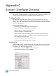
This appendix provides information for configuring a Sensor+ system to operate within the
UL924 specification.
Terminations
A dry contact closure (maintained recommended) must be wired to each rack containing
dimmers in the emergency look.
Configuration
Step 1: Login to the CEM+ with at least Power User Level of access.
• CEM+ face panel PIN: 3333
• Sensor+ Connect web interface - Login: power / password: powerpass
Step 2: Set the levels of the dimmers/lights you want in the emergency look to level of at
least the Panic Master Level in the CEM+ (80 to 100% - defaults to 100%).
Step 3: Record Panic on the CEM+. Be sure the configuration closure type matches your
actual physical closure type.
WARNING:
RISK OF ELECTRIC SHOCK! Failure to disconnect all power to the rack
before working in the rack could result in serious injury or death.
J3
To trigger Panic,
use a
Maintained
Closure
For remote
indication of
Panic activation,
wire to
external load
(such as a
lamp or relay)
+12Vdc
Turn on DMX termination
in the last rack that is
physically connected in
the DMX chain.
1234567812345678
J10J11
COM
n/c
n/c
n/c
n/c
n/c
n/c
n/c
n/c
n/c
n/c
Data + (Red)
Data - (Black)
From source
DMX A
If daisy-chaining to
another rack or
DMX device...
COM
Data + (Red)
Data - (Black)
From source
DMX B
If daisy-chaining to
another rack or
DMX device...
J3
To trigger Panic,
use a
Maintained
Closure
For remote
indication of
Panic activation,
wire to
external load
(such as a
lamp or relay)
+12Vdc