CEM+ Configuration Manual Version 1.2 C o p y r i g h t © E le c tr o n i c T h e a t r e C o n t r o l s , I n c . All Rights reserved. P r o d u c t in f o r m a t i on a n d s p e c i f i c a t i o n s s u bj e c t t o c h a n g e . P a r t N u m b e r : 7150M1400-1.2.
Table of Contents Introduction . . . . . . . . . . . . . . . . . . . . . . . . . . 1 Congratulations.... . . . . . . . . . . . . . . . . . . . . . . . . . . . . . . . . . . . .1 Using this Manual . . . . . . . . . . . . . . . . . . . . . . . . . . . . . . . . . . . .1 Chapter 1 Overview . . . . . . . . . . . . . . . . . . . . . . . . . . . . 2 System Components . . . . . . . . . . . . . . . . . . . . . . . . . . . . . . . . . .2 Sensor+ Connect Web Browser Interface Overview . . . . . . . . . .
Chapter 4 CEM+ Configuration Procedures . . . . . . . . 30 CEM+ Configuration Overview . . . . . . . . . . . . . . . . . . . . . . . . .30 Configuration Procedures. . . . . . . . . . . . . . . . . . . . . . . . . . . . . . . . .30 Configure Your Computer for an ETCNet2 Network . . . . . . . . .30 Software Changes [Power] . . . . . . . . . . . . . . . . . . . . . . . . . . . .31 Delete All Racks [Power]. . . . . . . . . . . . . . . . . . . . . . . . . . . . . .32 Configure/Confirm Network Settings of CEM+ .
Appendix C Sensor+ SineWave Dimming . . . . . . . . . . . 56 SineWave Benefits . . . . . . . . . . . . . . . . . . . . . . . . . . . . . . . . . .56 Configuration . . . . . . . . . . . . . . . . . . . . . . . . . . . . . . . . . . . . . . .56 D20SW Dimmer Module Default Properties . . . . . . . . . . . . . . .57 SineWave Differences You Need to Know . . . . . . . . . . . . . . . .57 Appendix D UL924 Setup . . . . . . . . . . . . . . . . . . . . . . . . 58 Introduction . . . . . . . . . . . . . . . . . .
Introduction Congratulations... on your purchase of an ETC Sensor®+ system. Sensor+ continues ETC's tradition of providing the highest quality products for the entertainment lighting market. Using this Manual This manual contains information on using and configuring features of the Sensor+ CEM+ in any Sensor+ rack or pack available up through the Power User login user level. The following symbols are used in this manual to alert you to danger or important information.
Chapter 1 Overview This manual covers functions and configuration of the CEM+ and Sensor+ Connect that are available to the Guest and User and Power User login levels.
Sensor+ Connect Web Browser Interface Overview The CEM+ module contains a web server that delivers graphical web pages for you to use during system configuration. The Sensor+ Connect Web browser interface can be used instead of the direct buttons on the CEM+ module itself. You can use an Ethernet-capable PC connected to the ETCNet2 network and running Windows 2000 or XP and Internet Explorer 6 or later to browse into any of the Sensor+ racks on the network.
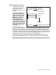
be assigned to any one of four Rooms in the configuration. Sensor+ systems can also have the Group play back a Preset in case of data loss. S e n s o r + C o n ne c t a n d W Y S I L i n k f o r F e e d b a c k Sensor+ Connect duplicates the functions of the CEM+ module on a PC or Emphasis Server on the ETCNet2 network. The Web browser interface allows you to monitor rack activity, reconfigure dimmer curves, record and activate presets, load and backup configurations, and many other features.
CEM+ Playback Priorities The CEM+ uses the same priority structure as all of the ETC products that use ETCNet2 and adds two more internally. Any incoming EDMX is reprioritized internally on the CEM+ as set on the patch page. The priorities of the EDMX sources (Emphasis, Obsession II, Unison, ETCNet2 DMX Node) are used to determine what level information makes it to the CEM+. That level information is then flatly re-prioritized to the level specified on the patch page.
Chapter 2 Basic Navigation This manual covers functions and configuration of the CEM+ and Sensor+ Connect that are available to the Guest and User and Power User login levels. The CEM+ User Interface User Level Default Guest User Power User PIN None 1111 2222 3333 You can access all the menus described in this chapter using the buttons on the face of the CEM+ module. Menus and messages are displayed on the integral 2x20 LCD display.
CEM+ Basi c Operation The procedures covered in this section are available to users logged in as Guest, which requires no password or PIN, and User and Power User which do require a password or PIN. The Main Menu The main menu is accessed using the and buttons on the CEM+ face panel. Each of the main menu items is described in the following pages. Each main menu item contains a number of sub-menus, each of which is illustrated in each section.
configuration for the local CEM+. The NoConfig menu has no login requirements and anyone has access to these menu items. Set Group / Rack The Set Group / Rack menu allows you to set the rack number of your local rack and the group number it belongs to. It also provides a place to set the network information (IP address, subnet mask and gateway IP). This should be done before creating a configuration.
Netw ork About Network provides the network settings for the currently selected rack. You can view the settings for any rack in the Group. Rack Data About Rack Data provides status information for the DMX and EDMX inputs for any rack in the Group. Rack Power About Rack Power provides status information for the line feed power and the voltage headroom settings for any rack in the Group. Identify Rack Identify Rack flashes the LCD and buttons on the face panel of the selected rack.
R e c o r d P r e s e t s [User ] The Record Presets menu allows a User to assign a preset number, and set the source for levels, the fade time and playback priority and the room. If the preset number is already recorded, you can record over it with the new settings, or if the preset is empty, you can record these settings to that selected number. S e t F a d e T i m e [ User ] The Set Fade Time menu allows a User to customize the fade time for a recorded preset.
at the CEM+. Levels set here take priority over any other level inputs, such as control consoles and architectural control systems. Levels set here do not take priority over levels generated by an active Panic look. The button on the CEM+ face panel accesses this menu directly. Release Levels The Release Levels menu allows you to release the level of a dimmer or a range of dimmers. Once released, those dimmers are available to other control inputs.
• Dynamic Preheat: this setting allows quick blackouts on dimmers that are set to preheat. Preheat settings are not available to the User level login. • DC Output Prevent: this setting offers protection on selected dimmers for loads that are sensitive to DC buildup, which can occur under certain conditions when positive and negative half-cycles become uneven. • Inrush Protection: this setting protects against large voltage increases in a single AC cycle.
Rack [User][Power] The Rack menu includes menus for setting the rack name and patch settings. The Rack menu is available only to those logged in at the User or Power User level. S e t G r o u p / R a c k [ Power] The Set Group / Rack menu allows you to set the rack number of your local rack and the group number it belongs to. This should be done before creating a configuration. Care and understanding should be used when making a change to these settings after a configuration is already loaded.
S e t N e t w o r k [User ] Set Network allows a User to enable or disable the network, enable or disable BootP (defaults to disabled) and set the network addressing for a selected rack. S e t F i r s t D i m m e r [ User] Set First Dimmer allows you to set the first dimmer number in a selected rack. For example, in a two SR48 rack Group, Rack 1 can be set with a First Dimmer of 1, and Rack 2 can be set with a First Dimmer of 97.
run for 15 minutes following a reset of the CEM+. G e t C o n f i g [ Power] After selecting this function, you will be prompted with the name of the rack (1-16) you want to get the configuration from. One option is Server which refers to an FTP server if one is configured on your lighting network. Please see the section FTP Server, page 43 for more information about setting up an FTP server for use with CEM+. It will then transfer the configuration to the local CEM+.
Chapter 3 Sensor+ Connect Web Interface Overview This section covers functions and configuration of the CEM+ and Sensor+ Connect that are available to the Guest and User and Power User login levels. User Level Default Guest User Power User Login [empty field] guest user power Password [empty field] guestpass userpass powerpass The web interface is a series of web pages intended to give you easier access to all of a CEM+ module’s features and settings.
Sensor+ Connect uses a navigation layout where the various main areas are selected on the left side of the page presenting sub-options. The right side of the page is used to view or edit the selected information. Note: The Emphasis Server network settings are the default ETC values and ready for immediate use. No configuration is required. You must set an IP address for any personal computer you plan to use on an ETCNet2 network.
Dimmer Check Also from the Group section is the Dimmer Check page. This page provides a quick and easy method to step through individual dimmers to do a dimmer check. Set dimmer number Set dimmer level Release current dimmer & apply level to previous dimmer Release current dimmer & apply level to next dimmer Start dimmer check Release current dimmer Racks & Dimmers All Racks All Racks provides a place to access and set the properties of all racks in the configuration.
Add Racks This page is where you add racks to your configuration. First dimmer of the first added rack. Enable Advanced Features for added racks. 240V changes the available rack & module types to European models. (Read below) Set initial patch mode. Set ambient temperature alarm. Set the default module type Set the dimmer balancing type To change the rack and module types to the European models, click the 240V check box.
Configure Rack This page is the individual rack equivalent to the All Racks/Configure Rack page listed above. See “All Racks” on page 18. Configure Dimmers This webpage provides a single place to set all of your dimmer’s properties. Below is a list explaining each one of the settings.
Set Dimmer Name [User] The Set Name menu allows a User to name a dimmer. Names are alphanumeric and can be up to 20 characters long (not all 20 characters may be visible on the LCD). Set Module Type [Power] The Set Module Type menu allows a User to set a dimmer or range of dimmers to a specific module type and firing mode. If the module is set to “Fluorescent”, you also set the threshold in this menu.
loads. When disabling Voltage Regulation, you should also set the Maximum Scale Voltage to a level well above the incoming line voltage to ensure that power wave is not clipped in any way. Preheat [Power] This setting enables/disables preheat for the selected dimmer. The preheat level is the Minimum Scale Voltage. Dynamic Preheat [Power] This setting allows quick blackouts on dimmers that are set to preheat.
Errors Errors for a rack can be viewed and cleared on this webpage. 1) To clear a specific error, click in the 2) Click the Clear Error(s) button. ...or... Click the Clear All Error(s) button to clear all errors regardless of Search The Search pages (search appears multiple times within the CEM+) allow you to find dimmers based on multiple search criteria. For example, you can search for all of the D20AF modules in rack 3 with a specific dimming curve.
You can also use the Configure Dimmers tab to modify the properties of all the found dimmers at once. (See below.) Use this section to make changes that will get applied to all found dimmers below. This section gets the changes applied to it. Apply to All makes the changes to the table Save Changes updates the information Rooms & Presets Assign Dimmers All dimmers in a group default to being in (and thus available only to) Room1.
Room (1-4) Clicking on a room in the navigation bar will bring up the display shown below. This is where you create presets, name presets, record or snapshot presets to give them level information or clear a preset to remove all level information from it. Indicates which room you are Creates a new preset to be named, recorded later. Indicates an inactive preset. Indicates which preset is being manipulated. Record will only use the level information set at the CEM+ in the preset.
as the port relative priority inside the CEM+, and any port’s data loss behavior on any of the Sensor+ racks. Along with the port settings are the standard patch settings. You can assign the starting DMX address for each rack’s data port (DMX & EDMX). Both must be checked for DMX Output from port B to work. DMX Port B Output is also enabled here. You need to enable both the Port B Output and the DMX B port of the last logical rack in the group.
While in Advanced Patch mode, port enable and data loss behavior are still set on the Port Settings page. Apply to All makes the changes to the table Use this section to do range patching. Save Changes updates the information Use this section to edit dimmer by dimmer for all ports. Port enables and data loss behaviors are still made on the Port Settings page.
Network The Network screen displays the network table for the CEM+. This information is local to the CEM+ and changing IP information here does not change the corresponding CEM+’s actual IP address. It only serves as a place to store and lookup the IP addresses of other CEM+s in the same group. This table does get shared to the other CEM+s in the group.
File Upload The File Upload web page is where you send either a configuration file or a software file to the CEM+ you are logged into. The CEM+ looks at the file being sent to automatically handle the file type or part of the configuration file. Load Management From this webpage, you can record, check, and clear load information for Advanced Feature modules (such as the D20AF).
Chapter 4 CEM+ Configuration Procedures CEM+ Configuration Overview Configuring a CEM+ from either the face panel via the LCD and buttons or the Sensor+ Connect web interface are basically the same procedures done in the same order. The web interface is more intuitive and you are able to make more changes simultaneously; making it a more efficient way to configure the modules. Please refer to the LCD menu structures and web interface site map for navigation details.
Browse into a CEM+ from Internet Explorer 6: Note: Step 1: Open Internet Explorer 6. Step 2: Type the IP address of the rack you want to browse to in the address box and press RETURN. Sensor+ Connect will open in the browser window if the CEM+ at the entered address is online. 10.101.101.101 is the default address for a CEM+ in the first rack of the first group. Your system may use a different addressing scheme.
• Step 6: After clicking Install, the software will be uploaded to the CEM+. While the software is being sent to the CEM+, the browser will no longer respond. After several minutes, there will be a pair of errors indicating that the CEM+ is done transferring the file and is now installing the software (and no longer communicating with Internet Explorer which is what causes the errors). After seeing the errors, it is safe to clear the errors (click OK) and close Internet Explorer.
Bui ld New Configuration (from NoConfig State) This overall procedure is made up of the next several smaller procedures. When a CEM+ is in the state of “NoConfig”, the face panel menu is different than during normal operation. It changes to options that are centered around getting the CEM+ configured. That menu can be found on the first page of “Appendix E: CEM+ LCD Menu” on page 60. From the NoConfig menu at the face panel you can Generate Defaults for that rack with a any user level including Guest.
• Every Group of racks must have a Rack 1. • Racks must be added sequentially, starting with rack 1 to a maximum of 16 racks. • For European rack and module options, set the voltage to 240V. • • [FP] This is straightforward in the face panel LCD menu (it’s the first setting). • [Web] However, the web interface requires that you click the 240V check box then Save Changes before the options will change.
advanced patch mode, however dimmers are not actually in dimmer doubling mode unless they are set with a Dimmer Double firing mode. It’s worth restating, that Standard Patch and Advanced Patch are handled as two completely separate patches including port enables, priorities and data loss behaviors. This means that if you configure the ports while in standard patch mode, switching to advanced patch mode will also switch those ports enables and data loss behaviors to a different configuration.
mode to Switched and turning on Voltage Regulation does not work. Property 120V 230V Firing Mode Normal Normal Curve Linear Linear Threshold 1% or desired setting 1% or desired setting Min. Scale Voltage 115V or desired setting 265V Max. Scale Voltage 115V or desired setting 265V Voltage Regulation Checked Checked Preheat Unchecked Unchecked Dynamic Preheat 0 sec. 0 sec.
values. Dimmer Doubling is only available for 120V systems. Property 120V 230V Firing Mode DimDbl --- Curve Mod-Square --- Threshold 1% --- Min. Scale Voltage 6V --- Max. Scale Voltage 115V --- Voltage Regulation Checked --- Preheat Unchecked --- Dynamic Preheat 0 sec. --- DC Output Prevent Checked --- InRush Protect Unchecked --- Currently, Dimmer Doubling works in Advanced Patch mode only.
Rooms & Presets Assign Dimmers to Rooms All dimmers in a group default to being in (and thus available only to) Room1. You can assign a dimmer or range of dimmers to any of the rooms (1-4), but to only one room at a time. Shown below, dimmers 101-112 are assigned to Room1 and dimmers 221-212 are assigned to Room2. Use this section to assign a range of dimmers to a room. Use this section to assign an individual dimmer to a room. Dimmers may only be assigned to a single room at a time.
Record vs. Snapshot a Preset Record and Snapshot are two different operations. Record will only use level information from Set Levels from the CEM+ modules in the group when storing a preset. Snapshot will use level information from all available sources to the CEM+ modules (DMXA, DMXB, EDMX, and Set Levels) when storing a preset. Activate/Deactivate a Preset You can toggle any preset on or off from either the web interface or the face panel LCD.
Load Management Load management can be used after your system is setup and your loads (lights) are connected to dimmers. For load management to work properly, Load Errors must be enabled for each dimmer you want to monitor. Load Errors is not enabled on any dimmers by default. Record Loads When you record loads, the CEM+ steps through a series of dimmer intensities and monitors the wattage as it proceeds. Only dimmers that have an initial intensity level greater than zero (0) are included in the process.
File Transfers The configuration files that are shared from CEM+ to CEM+ in a group are XML files that are sent and received via FTP (File Transfer Protocol). They are then parsed at each CEM+ for use locally within that CEM+ depending on the rack number (the CEM+ knows what rack number it is and looks to that part of the configuration to get it’s settings). There are four (4) separate files that make up the user-defined configuration. • Sensor.
Below is what the sensor.rak file looks like viewed in this manner. D o w n l oa d a C o n f i g u r a t i o n To download a configuration file to disk, just right-click on the file name and select “Save Target As...”. This will bring up a standard dialog box asking you to name the file and to pick a location to save it. It will append the file name with “.xml” instead of the file extension listed on the web page. This will not prevent you from uploading the configuration file to a CEM+ later.
FTP Server An FTP server can be configured to be on the ETCNet2 network and act as a file storage location for the configuration files of the group. An FTP server is not provided as standard with a CEM+. CEM+ modules can access any stock FTP server that is configured with the following minimum settings: • IP address of the FTP server needs to match the one specified in the network table in the configuration.
Chapter 5 Service Contacting ETC about Equipment Problems If you are having difficulties, your most convenient resources are provided in this user manual. To search more widely, try the ETC website at www.etcconnect.com. If none of these resources is sufficient, contact ETC Technical Services directly at one of the offices identified below.
Changing Installation Rack Modules All Sensor+ rack dimmer modules can be easily replaced without tools. Modules slide in and out of their slots and are ready to start dimming immediately. Although Sensor modules, including the CEM+, can be replaced with power on, always turn rack power off at the main circuit breaker, if possible, before changing modules.
Remove a CEM+ Module: Step 1: Turn off rack power at the main breaker. Step 2: Open the rack door. • Please see Releasing and Securing Module Safety Stops (ESR Racks Only) above if appropriate. Step 3: Press the “eject” symbol on the right end of the spring-loaded handle and grab the other end of the handle, pulling it until it is perpendicular to the face of the CEM+. The CEM+ will be gently pushed out of the rack as you move the handle. Step 4: Pull the CEM+ straight out. Press here to insert.
CEM+ Fuses The CEM+ has two fuses: • The F1 fuse is a 250V, 0.75 amp, fuse. CEM+ operating power and power for the dimmer module electronics, is drawn through this fuse. If F1 fails, the CEM+ will not operate and dimming will not work. The Sensor+ rack beacon will be dark. The fuse in the F2 position is a spare 0.75 amp fuse. • Phase F3 fuse is a 250V, 5 amp fuse. Power for the rack’s fan is drawn through this fuse. If F3 fails, the fan will stop running and the CEM+ will display an air flow error.
Troubleshooting Your Sensor+ system helps you identify system problems with status reporting and diagnostic testing capabilities. You will usually notice a system problem in one of two ways: • The Sensor+ beacon on the dimmer rack begins blinking, indicating the CEM+ has detected a problem. The system may still continue to dim normally. • You notice a problem with system performance. The beacon may be flashing, or the problem may be caused by another part of your lighting control system.
49 Sensor+ CEM+ Configuration Manual
Appendix A CEM+ Error Messages If the CEM+ detects an error, it will flash the beacon and display the appropriate error message on the LCD display. A CEM+ will only display error messages for the same rack it is in - you can’t browse to other racks to view their errors from a single CEM+. Errors are also displayed in the WYSILink Message Log on Emphasis Control Systems and WYSILink PCs on the network.
CEM+ Error Message Probable Cause Possible Corrective Action PHASE (A, B or C) VOLTS LOW Voltage on phase (A, B or C) is lower than 80Vac. Check line feed. LOW AIRFLOW Airflow is low. Check fans and air filter for obstruction. CLEAN YOUR FILTER This is a reminder to clean your air filter. It appears when the “Clean Time” clock has counted down to zero. Reset the “Clean Time” counter to the number of hours you want between filter cleaning.
Appendix B Dimmer Curves Dimmer curves determine how dimmers set voltage output in response to control signal input. To accommodate designer preferences and load response variations, Sensor offers five dimmer curve choices, which can be applied to individual dimmers. Linear curve The linear curve matches the control input percentage to Root Mean Squared (RMS) voltage output. Each percent increase in control level increases dimmer voltage output by the same amount .
Modified linear curve A modified linear curve reduces the voltage change at low control levels for better performance in low-wattage fixtures. Output % of Scaled Voltage Linear Curve 100 83 66 50 33 16 0 1 10 20 30 40 50 60 70 Console percentage setting Modified linear curve 80 90 100 (for reference) Linear curve Square law curve At low control levels, much of traditional incandescent fixture’s light output is in the invisible infrared spectrum.
Modified Square law curve A standard square law curve may overcompensate for infrared loss, resulting in “steppy” response to incremental control changes at low levels.
55 Sensor+ CEM+ Configuration Manual
Appendix C Sensor+ SineWave Dimming This appendix provides information for configuring a Sensor+ system that includes one or more UL and cUL approved Sensor+ SineWave dimmer installation racks. SineWave Benefits Sine wave dimming provides “silent dimming” by controlling the power in a way that maintains a clean sinusoidal wave form to your fixtures and does not create any “lamp noise” or “buzz”. Due to the added level of control, ETC SineWave dimming also provides superior voltage regulation.
D20SW Dimmer Module Default Properties Property 120V Firing Mode Normal Curve Mod-Square Law Threshold 1% Min. Scale Voltage 6V Max. Scale Voltage 115V Voltage Regulation Checked Preheat Unchecked Dynamic Preheat 2 sec. DC Output Prevent * Unchecked InRush Protect ** Unchecked Advanced Features (AF) Checked Load Errors Checked AF Sensitivity 5 AF Reaction 10 sec. Scale Load 35% * ETC sine wave dimming produces no DC component so this function is unnecessary.
Appendix D UL924 Setup I n t r o d u c ti o n This appendix provides information for configuring a Sensor+ system to operate within the UL924 specification. WARNING: RISK OF ELECTRIC SHOCK! Failure to disconnect all power to the rack before working in the rack could result in serious injury or death. Terminations A dry contact closure (maintained recommended) must be wired to each rack containing dimmers in the emergency look.
CEM+ LCD Panic Menu: ETC CEM+ R__/__ G__ Panic >Active< Panic Activate Panic Panic Activated Panic Record Panic Force Others Off Record Panic Master Level [100]% [Disabled] Panic already Rec? No Yes Overwrite Panic? Panic Recorded Yes Overwrite? [No} No Panic Clear Panic Clear Panic Panic Cleared Panic Panic Switch type Panic Switch Action Updating Settings Configure Switches [Normally-Open] [Maintained] Please Wait S e n s o r + C o n ne c t w e b i n t e r f a c e ( C o n f i g
Config is checked vs. backplane On Power UP of CEM+ E CEM+ LCD Menu yes If Valid Config No Enabled Network Enable [Enabled] Select Rack name >Rack Name< No Config R__/ 0 G__ [Setup Network] Rack 1 Successful Config loaded from Load Config from Select Config [__] [___] C [Standard] Rack Set Alarm Temp Set Address Mode No Config R__/ 0 G__ Rack Number [__] Set Group / Rack Set Group / Rack Group Number [__] __ * [Generate Defaults] __ [Disabled] [www.xxx.yyy.
61 Sensor+ CEM+ Configuration Manual Home (<<) to Exit [Rack Error(s)] ETC CEM+ R__/__ G__ >11111.0.0.9.0.
E CEM+ LCD Menu 62 0 0 >ppp< [Room Name] Set Active Presets Select Room >r< [Room Name] Setup Preset Max Active Presets [a] Active Presets Name Room r Name Room Room Number [r] Setup Preset Set Room Name Please Wait Updating Settings Please Wait Updating Settings Name Preset [Preset Name] Name Preset Preset Number [ppp] Please Wait [10] Setup Preset [Preset Name] Select Preset Set Preset Name Set Priority Setup Preset Updating Settings Please Wait Set Priority >ppp< Updating
63 Sensor+ CEM+ Configuration Manual Panic Switch type [Normally-Open] Panic Configure Switches Clear Panic Panic Cleared Panic Clear Panic Record Panic Master Level [100]% Panic Activated Panic Activate Panic Record Panic Panic >Active< Panic Panic Menu ETC CEM+ R__/__ G__ Updating Settings Please Wait Yes [Maintained] No Overwrite? [No} Overwrite Panic? Yes Panic already Rec? Panic Switch Action [Disabled] Force Others Off Panic Recorded No
E CEM+ LCD Menu 64 Set Module Type Module = [list] Set Levels >xx< Thru Dimmer [xxxxx] Set Module Type Thru Dimmer [xxxxx] Set Levels From Dimmer [xxxxx] Dimmer Release Levels Name Dimmer Set Curve From Dimmer [xxxxx] Name Dimmer Select Dimmer >xxxxxx< Setup Dimmer Set Curve Setup Dimmer Set Dimmer Name Dimmer Check First Dimmer >xxxxxx< Dimmer Check Set Level >xxx< Dimmer Dimmer Check + or - Dimmer[xxxxx] Dimmer Check Off >ON< ON Please Wait Updating Settings >ON< Report Load Er
65 Sensor+ CEM+ Configuration Manual Rack Name Rack >#< Select Rack > #/ #< [Rack Name]* Setup Rack Set Rack Name EDMX Priority [xx] [Enabled] Set DMX A [Rack Name]* Set EDMX If disabled Set EDMX [Enabled] Set Rack Data Mode Standard Advanced CH>xxxxx< DD[zzzzz] Set EDMX >xxxxx< Set EDMX DMX Length [xxx] Set EDMX DMX Start [xxxxx] EDMX Priority [xx] If disabled Set DMX B Priority Set DMX B [Disabled] Set DMX B Standard Advanced Set DMX B DMX Length [xxx] Advanced Set DMX B Mod
E CEM+ LCD Menu 66 Please Wait Updating Settings Network Enable [Enabled] Set First Dimmer Dimmer [xxxxxx] Set Temp Alarm Select Rack > #/ #< [Rack Name] Select Rack > #/ #< [Rack Name]* Select Rack > #/ #< [Rack Name]* Setup Rack [Set Network] Setup Rack [Set First Dimmer] Setup Rack [Set Temp Alarm] Updating Settings Please Wait Updating Settings Advanced Features [off] Configure Fan [No Data/15 Min] Select Rack > #/ #< [Rack Name]* Select Rack > #/ #< [Rack Name]* Setup Rack
67 Sensor+ CEM+ Configuration Manual Network Defaults [No] Setup Rack Please Wait [Network Defaults] Updating Settings Setup Rack Please Wait [Delete All Racks] Updating Settings Setup Rack Please Wait [NAMENNNNNNNNNN] [Get Config] [Send Config To All] Updating Settings Get From Rack [xx] Setup This Rack Rack Menu (cont.
E CEM+ LCD Menu 68 Set PIN Power User User Level [mm] Minutes Setup Group Set Login Timeout Setup Group GMT [- 6] Set Login Timeout Set Time Zone Setup Group Set Time Zone User Updating Settings Set Temp type Report as [F] Setup Group Ambient Temp Type Enter New PIN PIN: [X X X X] Select Access Level [Power User] Enter New PIN PIN: [X X X X] [User] Select Access Level Please Wait Updating Settings Please Wait Please Wait [English] Updating Settings Set Language Please Wait Upd
69 + All racks + Add racks + Individual rack select + Search Racks & Dimmers + Summary + Set dimmer levels + Dimmer check + Search Group Login Screen • Find dimmers in group Search • Status Individual Rack Select • Add racks to group • Delete all racks in group Add Racks • Rack name & type • Rack power per phase & frequency • Ambient rack termperature All Racks • Find dimmers in group Search • Set dimmer to level • Release & go to the next dimmer • Release & go to the previous dimmer • Relea
F Sensor+ Connect Site Map 70 + Panic + Patch + Network + File transfer + File upload + Load Management Configuration + Room 1 + Room 2 + Room 3 + Room 4 + Assign Dimmers Rooms & Presets • View individual dimmer recorded loads and actual loads • Load check • Record loads • Clear loads Load Management • Upload CEM+ software to local CEM+ • Upload configuration file to local CEM+ File Upload • Get a configuration from another CEM+ • Send local configuration to all other CEM+s in group • View config
Corporate Headquarters 3031 Pleasant View Road, P.O.