
User manual


appendix a installation 319
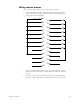
Wiring remote macros
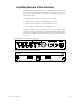
There are three typical ways to wire the Remote Go function:
• Connect all -Macro pins (pins 1-8) to ground (pin 10) and switch the
leads connecting the +Macro pins (pins 14-21) to +12 Vdc (pin 24) as
shown in the following diagram.
• Connect all +Macro pins (pins 14-21) to the +12 Vdc pin (pin 24) and
switch the leads connecting the -Macro pins (pins 1-8) to the ground
(pin 10).
• Provide your own power supply that generates a 12 Vdc potential be-
tween the +Macro and -Macro pins and switch either of these leads.
-Macro 1,901
-Macro 1,902
-Macro 1,903
-Macro 1,904
-Macro 1,905
-Macro 1,906
-Macro 1,907
-Macro 1,908
not connected
not connected
not connected
+12 Vdc
Ground
1
2
3
4
5
6
7
8
9
10
11
12
13
+Macro 1,901
+Macro 1,902
+Macro 1,903
+Macro 1,904
+Macro 1,905
+Macro 1,906
+Macro 1,907
+Macro 1,908
not connected
not connected
+12 Vdc
Ground
14
15
16
17
18
19
20
21
22
23
24
25