
User manual


appendix a installation 311
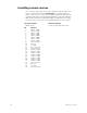
Installing Remote Video Interface
The Remote Video Interface allows you to attach Expression peripherals
to your network. Each Remote Video Interface contains connectors for
three types of network cable. Choose the connector that matches your
network cable type.
To install the Remote Video Interface, follow these steps:
1. Plug the network cable into the appropriate connector.
2. Plug the power cable into a grounded 120 VAC outlet.
3. If necessary, set DIP switches as described below.
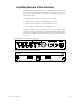
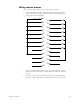
The Remote Video Interface provides ports for remote accessories. It sup-
ports two monitors, an alphanumeric keyboard and an RFU, and provides
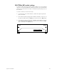
a serial port for a digitizer. The illustrations below show the Remote Video
Interface’s front and back panels and indicate the connector used by each
accessory.
ETCNet Remote Video Interface back panel
ETCNet Remote Video Interface front panel
1.5A FB
Serial #:
Model #:
3030 Laura Lane, Middleton, Wisconsin 53562-1754
Electronic Theatre Controls, Inc.
Product:
CRT Displays
CRT 1
Digitizer/Serial
FUSE
CRT 2
6.25A SB
FUSE
120 VAC 50/60 Hz
120 VAC 50/60 Hz
ETCNet RS-232
RFUKeyboard
Switched Outlets AC Input
Off
On
Power
PUSH
RFU
ETCNet Packet In
CPU Running
Console Connection
ETCNet Packet Out
ETCNet
remote video interface