
User manual


310 Insight 2x user manual
DIP switch and jumper settings
The Remote Interface’s main circuit board contains one 8-switch DIP
switch unit at location S1 and a set of 14 jumpers at location J22. In order
to activate the Remote Interface, you must first adjust the settings on
these jumpers and switches.
1. Remove the screws that secure the top panel.
2. Raise the top panel to expose the internal circuitry.
3. Locate jumpers 1 through 14. (location J22)
4. If your network cable is plugged into the BNC connector (ThinNet),
install jumpers 1 through 6. Be certain jumpers 7 through 12 are not
installed.
5. If your network cable is plugged into the RJ45 connector (Twisted
Pair) or the DB15 connector (ThickNet), install only jumpers 7 through
12. Be certain jumpers 1 through 6 are not installed.
6. Jumper 13 must always be off. Jumper 14 should always be installed.
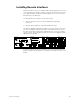
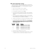
7. Locate the DIP switches at location S1 on the corner of the circuit
board nearest the power switch. Switches are either On (Closed) or
Off (Open). DIP switch 1 must be Off and 2 must be On or the
Remote Interface will not start. Adjust the settings as necessary to
match the table below.
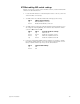
DIP Switch Position Function
1 Off (Open) Normal operation, Factory Use Only
2 On (Closed) Normal operation, Factory Use Only
3 Off (Open) Normal operation, Factory Use Only
4 Off (Open) Normal operation, Factory Use Only
5 Off (Open) Normal operation, Factory Use Only
6 Off (Open) Normal operation, Factory Use Only
7 Off (Open) Normal operation, Factory Use Only
8 Off (Open) Normal operation, Factory Use Only
8. Close the face panel and replace the screws.
9. The Remote Interface checks DIP switch settings when it is turned
on
.
Restart the unit for new DIP switch settings to take effect.