
Specifications


Insight 3 User Manual, v.3.1 347
Appendix B
References
DIP switches in earlier consoles
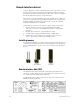
Some models sold before Insight 3 had DIP switches located on the
console’s main processor board. Identify these consoles by the presence
of a power keyswitch on the right side of the console’s face panel.
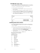
To gain access to these internal DIP switches, raise the console’s face
panel as explained under Opening the console, page 324. The main
processor board appears as shown below.
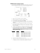
When installing ETCNet, Full Tracking Backup or SMPTE for an earlier
model console, adjust the processor board’s DIP switches according to
the information below.
Switch packages S1 and S2)
These switches are moved with a sharp pointed object. ON is labeled.
1. If using Twisted Pair wiring (RJ45 connector) for ETCNet, set all
switches of S1 to ON and set all switches of S2 to OFF.
2. If using ThinNet wiring (BNC connector) for ETCNet, set all switches
of S1 to OFF and set all switches of S2 to ON.
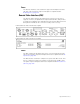
Switch package S4
These are rocker switches. OPEN is labeled. Rock toward OPEN to set the
switch to OPEN.
1. Set DIP switch 1 to OPEN.
2. Set DIP switches 2 and 3 to indicate ETCNet network status. (If you
are using Full Tracking Backup, the switches also determine which
console is A and which is B).
DIP 2 DIP 3 Console mode on start up
OPEN OPEN Network off
CLOSED CLOSED Network on/Single console
CLOSED OPEN Network on/FTB Console A
OPEN CLOSED Network on/FTB Console B
3. Set DIP switch 4 for SMPTE
DIP 4 SMPTE status
OPEN Disabled
CLOSED Enabled
4. Set DIP switches 5 through 8 to OPEN.