
User's Manual
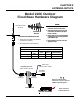
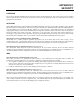
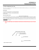
Table Of Contents
- 210 User's Manual Front Cover
- Chapter 0 - Table of Contents
- Chapter 1 - Introduction
- Chapter 2 - Starting Out
- Chapter 3 - Example Applications
- Chapter 4 - Utilities and Features
- Chapter 5 - Web Configuration Manager
- Chapter 6 - Serial Configuration and Applications
- Chapter 7 - Repeating and Mesh Networking
- Chapter 8 - Antenna Setup
- Apx B - Interface Ports
- Apx C - Radio Configuration
- Apx D - Security
- Apx E - Troubleshooting
- Apx F - 210C Specifications
- Apx F - 210M Specifications

CHAPTER 8
ANTENNA SETUPS
Model 210C Outdoor
Fixed Base Hardware Diagram
NOTES
1. Use coax cable runs as short as
practical to minimize cable losses.
2. Vapor wrap all external antenna coax
connections with Silicone tape (EST
Part No. AA243).
3. Contact ESTeem for recommendations
regarding antenna mounting hardware
and installation tips.
4. Ground antenna structure, base and
lightning arrestor.
Directional
Antenna
Directional
Antenna
Omni-Directional
Antenna
ANTENNA RECOMMENDATIONS
1. Omni-Directional (EST P/N AA20C.1
or FG4507 & FG4607).
2. Directional (EST P/N AA202C.1).
Antenna Feedline Recommendations
EST Antenna Part No.
Feedline
Type
20C.1 202C.1 FG4507/FG4607
< 50 ft. Length RG-8 AA237 AA237 AA237
> 50 ft. Length Helaix AA236 AA236 AA236
N Male
Connector
N Male
Connector
TNC Male
Connector
RG-8 Coax
EST Part No. AA234
Lightning Arrestor
(EST Part No. AA161)
Earth Ground
Ethernet and RS-232C
Interfaces to User’s Devices
USB Programming Port
Power Interface
Cable/Connector
12 VDC Power Supply
(
EST Part No. AA178)
12 VDC Power Supply
(
EST Part No. AA178)
Revised: 4 Mar 2013 8-3 EST P/N AA107-210CM