
User's Manual

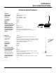
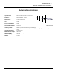
Table Of Contents
- 210 User's Manual Front Cover
- Chapter 0 - Table of Contents
- Chapter 1 - Introduction
- Chapter 2 - Starting Out
- Chapter 3 - Example Applications
- Chapter 4 - Utilities and Features
- Chapter 5 - Web Configuration Manager
- Chapter 6 - Serial Configuration and Applications
- Chapter 7 - Repeating and Mesh Networking
- Chapter 8 - Antenna Setup
- Apx A - FCC Information
- Apx B - Interface Ports
- Apx C - Radio Configuration
- Apx D - Security
- Apx E - Troubleshooting
- Apx F - 210C Specifications

APPENDIX F
210C SPECIFICATIONS
Antenna Specifications
Revised: 5 Dec 12 APX F-4 EST P/N AA107-210CM
Model AA202C/F
Model No: AA202C & AA202F
Antenna Type:
Directional, DC grounded, 5 element yagi.
Applications: Fi
xed base.
Frequency:
450 to 470 MHz - AA202C
400 to 420 MHz - AA202F
Polarization:
Vertical
or Horizontal
Impedance: 50
ohms
Gain: 10 dB
VSWR: <
1.5
Front To Back Ratio: 20 dB
Horizontal Beamw
idth: 59 degrees
Vertical Beamwidth:
53 degrees
Antenna Material:
High strength aluminum with gold chromate finish.
Mounting Hardware:
Heavy duty U bolts for mounting up to 2 1/8 in. pipe with right angle mount or direct panel
mount.
Antenna Connector: N-Ty
pe Female
Maximum Power Input: 300 W
atts
Antenna Envelope:
34.5 in. length by 13.25 in. width
Windload (RWV): 100
mph
Weight: 1.68 lb
s.