
User's Manual
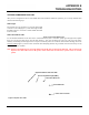
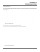


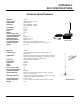
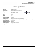
Table Of Contents
- 210 User's Manual Front Cover
- Chapter 0 - Table of Contents
- Chapter 1 - Introduction
- Chapter 2 - Starting Out
- Chapter 3 - Example Applications
- Chapter 4 - Utilities and Features
- Chapter 5 - Web Configuration Manager
- Chapter 6 - Serial Configuration and Applications
- Chapter 7 - Repeating and Mesh Networking
- Chapter 8 - Antenna Setup
- Apx A - FCC Information
- Apx B - Interface Ports
- Apx C - Radio Configuration
- Apx D - Security
- Apx E - Troubleshooting
- Apx F - 210C Specifications

APPENDIX F
210C SPECIFICATIONS
Antenna Specifications
Revised: 5 Dec 12 APX F-3 EST P/N AA107-210CM
Model No: AA19C
Antenna Type: Om
ni-Directional, ½ Wave
Model AA19C
Applications: Mobile Mount.
Frequency:
450 to 470 MHz - AA19C
400 to 420 MHz - AA19F
Polarization:
V
ertical
Impedance: 50
ohms
Gain: 2 db.
VSWR: <
2 to 1
Front To Back Ratio: n/a
Horizontal Beamw
idth: n/a
Vertical Beamw
idth: 60 degrees
Antenna Material:
Rubber duck whip.
Mounting Hardware:
Magnetic base.
Antenna Connector:
TNC with 12 feet integral RG-58 cable.
Antenna Envelope: 16 in
. length. Magnetic base 3.5 in. by 3 in by 1 in.
Weight: 1 lb. 5 oz.
Model
No: AA20C.1
Antenna Ty
pe: Om
ni-Directional, DC grounded, Collinear 5/8 wave
over 1/2 wave.
Model AA20C.1
Applications:
Fixed base or mobile mounting. L shaped mounting bracket
may be removed for panel mounting. Ground plane radials
may be removed depending on application.
Frequency: 450 to 470 MHz - AA20C.1
Polarization: V
ertical
Impedance: 50
ohms
Gain: 4.5 dB.
VSWR: <
1.5
Front To Back Ratio: n/a
Horizontal Beamw
idth: n/a
Vertical Beamw
idth: 30 degrees
Antenna Material:
Stainless steel whip and ground plane radials. All other
hardware anodized metal.
Mounting Hardware:
Stainless steel clamps for mounting to ¾ in. to 1 /2 in. pipe
with right angle mount or direct mount.
Antenna Connector: N-Ty
pe Female
Antenna Envelope: 37 ½ in
. length by 16 in width with ground plane radials.
Weight: 2 lbs.