
User's Manual
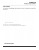
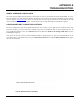

Table Of Contents
- 210 User's Manual Front Cover
- Chapter 0 - Table of Contents
- Chapter 1 - Introduction
- Chapter 2 - Starting Out
- Chapter 3 - Example Applications
- Chapter 4 - Utilities and Features
- Chapter 5 - Web Configuration Manager
- Chapter 6 - Serial Configuration and Applications
- Chapter 7 - Repeating and Mesh Networking
- Chapter 8 - Antenna Setup
- Apx A - FCC Information
- Apx B - Interface Ports
- Apx C - Radio Configuration
- Apx D - Security
- Apx E - Troubleshooting
- Apx F - 210C Specifications

APPENDIX E
TROUBLESHOOTING
Revised: 5 Dec 12 APX E-4 EST P/N AA107-210CM
SIGNAL STRENGTH VS DATA RATE
The average signal strength required to maintain a specific data rate will vary by ESTeem 210 model and bandwidth. To review
the required signal level and its effect from distance and hardware selected, please use the ESTeem RF Design program available
from our web site (
www.esteem.com
). Please note that the data rates can be greatly affected by overall activity on the radio
channel and the total background noise. These values should be used as a guide, but testing after installation is required.
LONG RANGE POINT TO POINT APPLICATIONS
The factory configuration on the 210 is optimized for distances up to 10 miles. If your application has an RF link with a range
greater than 10 miles, you will need to set the maximum range value on both ESTeem 210’s on this communication link. To
access the Maximum Distance value select Advanced from the top Menu then Wireless LAN Settings>wlan0 device and press
the Next button (Figure 5).
Scroll down the menu list until you find the Maximum Distance variable (Figure 6). Enter the maximum distance of the
co
n
nection in miles. At the bottom of the screen press Return to Advanced button and then Commit and Reboot button (Figure
5) to save the information.
Figure 5: Advanced Features Screen
Figure 6: Maximum Distance Value Entry