
User's Manual
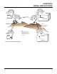
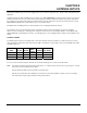
Table Of Contents
- 210 User's Manual Front Cover
- Chapter 0 - Table of Contents
- Chapter 1 - Introduction
- Chapter 2 - Starting Out
- Chapter 3 - Example Applications
- Chapter 4 - Utilities and Features
- Chapter 5 - Web Configuration Manager
- Chapter 6 - Serial Configuration and Applications
- Chapter 7 - Repeating and Mesh Networking
- Chapter 8 - Antenna Setup
- Apx A - FCC Information
- Apx B - Interface Ports
- Apx C - Radio Configuration
- Apx D - Security
- Apx E - Troubleshooting
- Apx F - 210C Specifications

CHAPTER 8
ANTENNA SETUPS
Revised: 5 Dec 12 8-1 EST P/N AA107-210CM
ESTeem offers different types of antennas ranging from ¼ wave to 5/8 wave in physical size. The user choice is dependent on the
application.
Communications in the VHF and UHF bands are normally over "Line of Sight (LOS)". Looking from
the antenna of one wireless
modem you must be able to see the antenna of the wireless modem you wish to communicate with. If a large object obstructs the
line of sight view it is unlikely that satisfactory communications will result. This means you must relocate the antennas or use the
REPEATER FEATURE and a second modem to go over or around the object.
The Model 210C and 210M products are allowed by the FCC to use high gain directional antennas.
It is noted that a ¼ wave antenna that does not have ground pl
ane radi
als requires a ground plane to operate at maximum
efficiency. This can simply be a conducting surface under the antenna that is a ¼ wavelength in diameter. For the Model 210C
(450-470 MHz) this is approximately 6.5 inches. A conducting surface can be anything from the rooftop of an automobile to a file
cabinet.
COAXIAL CABLES
To minimize signal loss, the overall length of the coaxial cable should be as short as possible. To avoid corrosion select coaxial
cabl
e
manufacturers with tinned copper braid, where possible. Listed below are representative cable losses in db/100ft at the VHF
and UHF frequencies:
Frequency
(MHz)
RG-58u
LMR 195
RG-8
(solid)
LMR600
1/2" Heliax
150-174 -5.2 -4.4 -1.7 -0.964 -0.88
402-420 -8.4 -7.8 -2.9 -1.72 -1.36
450-470 -9 -7.8 -3 -1.72 -1.45
In a severe noise environment it may be desirable to use a double shield type of coax cable such as RG-214/U.
Note: Pre-made coax cabl
es can be purchased f
rom the factory. A -3 dB loss means you have lost 1/2 of your signal. A +3 dB
gain means you have doubled (x2) your signal.
Keep the antenna feedline as short as possible to minimize losses.
Extreme care must be taken when attaching coax connectors to the antenna feedlines. If there is any error in making
th
is co
nnection the output of the transmitter will be greatly reduced.