
User's Manual


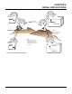

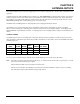
Table Of Contents
- 210 User's Manual Front Cover
- Chapter 0 - Table of Contents
- Chapter 1 - Introduction
- Chapter 2 - Starting Out
- Chapter 3 - Example Applications
- Chapter 4 - Utilities and Features
- Chapter 5 - Web Configuration Manager
- Chapter 6 - Serial Configuration and Applications
- Chapter 7 - Repeating and Mesh Networking
- Chapter 8 - Antenna Setup
- Apx A - FCC Information
- Apx B - Interface Ports
- Apx C - Radio Configuration
- Apx D - Security
- Apx E - Troubleshooting
- Apx F - 210C Specifications

CHAPTER 7
REPEATING FEATURES
Revised: 5 Dec 12 7-5 EST P/N AA107-210CM
The Root Bridge will be selected in one of two ways: the Root Bridge can be manually set (recommended) during the
configurat
ion of the Repeater Peer table (Figure 3) or the Root Bridge designation will default to the lowest MAC address of all
the Model 210’s in the network. The manual Root Bridge configuration is located in the “Advanced Settings” section.
Redundant Backup
Figure 4: Redundant Backup Diagram
The ESTeem Model 210 configured in Access Point Repeater
mode will autom
atically function as a redundant backup if two
Model 210’s are installed at the same location (Figure 4). If two
Model 210’s are connected to the same switch, one of the Model
210’s will be Blocked when the Spanning Tree Protocol is
completed. The network will continue to use this route until any
problem with the original Model 210 is detected and the second
Model 210 will begin operation at that site.
Redundant Master Configuration
The configuration in Figure 4 will also provide a redundant
backup for th
e Master Site (Root Bridge). Configure both Model
210’s as Root Bridges (see above) giving the primary Root
Bridge a value of 1 and the secondary Root Bridge a value of 2.