
User's Manual
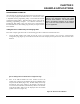
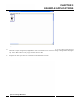
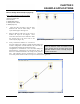
Table Of Contents
- 210 User's Manual Front Cover
- Chapter 0 - Table of Contents
- Chapter 1 - Introduction
- Chapter 2 - Starting Out
- Chapter 3 - Example Applications
- Chapter 4 - Utilities and Features
- Chapter 5 - Web Configuration Manager
- Chapter 6 - Serial Configuration and Applications
- Chapter 7 - Repeating and Mesh Networking
- Chapter 8 - Antenna Setup
- Apx A - FCC Information
- Apx B - Interface Ports
- Apx C - Radio Configuration
- Apx D - Security
- Apx E - Troubleshooting
- Apx F - 210C Specifications

CHAPTER 3
EXAMPLE APPLICATIONS
Ethernet Bridge Mode Example 1 (Figure 1)
Point to Point Ethernet Bridge
(2) ESTeem Model 210
Serial Numbers: E-14000 (Main Office) and E-14001 (Remote Office)
1. Add
the two ESTeem Model 210s to the network using the above procedure. Once both ESTeem 210s are on the
confi
guration page, create a wireless link by
clinking on one of the two connection boxes and
dragging a line to the other modem (Figure 13).
Revised: 5 Dec 12 3-7 EST P/N AA107-210CM
5. Verify both ESTeem modems are connected to
th
e same switch as the computer running the
ENC Utility and send the configuration to both
modems at the same time by selecting
ESTeem>ESTeem Configuration>Send
Configuration to All ESTeems (Figure 14).
6. Once the ENC Utility has downloaded the
confi
guration for both ESTeem 210s, the status
box around the ESTeems will change from
yellow to blue. This indicates that the
configuration was completed successfully and
the ESTeem 210s are ready to be installed in the
application.
Figure 13: Create Wireless Link
Figure 14: Send Configuration to ESTeems