
User's Manual

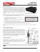
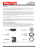
Table Of Contents
- Chapter 0 - Front Cover 195CM
- Chapter 0 - Table of Contents 195CM
- CHAPTER 1 – Introduction
- Before You Begin
- Model 195C/M Overview
- Three Configuration Phases
- Model 195C/M Hardware Description
- Modes of Operation Description and Examples
- Programming Examples
- CHAPTER 5 – Web Configuration
- Logging Into Web Configuration Manager
- Web Configuration Manager
- CHAPTER 6 – Serial Configuration and Applications
- Using USB Programming Port
- Using RS-232 Data Port
- ESTeem Mesh Network
- Rapid Spanning Tree Protocol (RSTP)
- Spanning Tree Protocols (STP)
- Redundant Backup
- CHAPTER 8 – Antenna Setups
- Antenna and Cable Configurations
- Weatherproofing Coaxial Cable Connections
- APPENDIX A – FCC Information
- APPENDIX B – Interface Ports
- APPENDIX C – Radio Configuration
- APPENDIX E – Troubleshooting
- APPENDIX F – 195C/M Specifications
- CHAPTER 1 – Introduction
- Chapter 1 - Introduction 195CM
- BEFORE YOU BEGIN
- MODEL 195C/M OVERVIEW
- The ESTeem Model 195C and 195M are wireless modem transceivers that can be used to build many types of Wireless Local Area Networks (WLAN). The ESTeem 195C/M series have multiple serial (RS-232, RS-422 and RS-485), Ethernet and 4/20mA sensor interfaces. The Model 195C and 195M can be configured for multiple modes of operation depending upon the needs of the wireless and wired network. The following interface configurations are provided as an overview of the basic network types, as all possible network configurations can not be listed. For further help in selecting the correct network type, please refer to Chapter 3 of this User’s Manual or call Customer Support at 509-735-9092.
- SERIAL APPLICATIONS
- ETHERNET APPLICATIONS
- Chapter 2 - Starting Out 195CM
- Chapter 3 - Example Applications 195CM
- Chapter 4 - Repeating 195CM
- Chapter 5 - Ethernet Configuration and Applications 195CM
- Chapter 6 - Utilities and Features 195CM
- ESTeem Network Configuration Utility (ENC)
- Note: The ESTeem Resource Disk is a stand-alone copy of the ESTeem Web site (Figure 2). Navigation of the Resource Disk is as simple as using your web browser. All technical documentation, User’s Manuals and the ESTeem Utility Program are available on the disk.
- Note: If the page does not auto load, open your web browser and set your address line to D:\index.html (Where D: is the drive letter for your CD-ROM drive).
- Note: This program is saved in a compressed file format.
- Note: The SSID, Mode of Operation and Modem ID will be adjusted through the ENC Utility or the Web Configuration Manager...
- Note: The ESTeem Resource Disk is a stand-alone copy of the ESTeem Web site (Figure 1). Navigation of the Resource Disk is as simple as using your web browser. All technical documentation, User’s Manuals and the ESTeem Utility Program are available on the disk.
- Note: If the page does not auto load, open your web browser and set your address line to D:\index.html (Where D: is the drive letter for your CD-ROM drive).
- Note: This program is saved in a compressed file format. Microsoft Windows XP® will open the file directly, but other operating systems will require a common compression program such as WinZip available for download at http://www.winzip.com
- Note: This Utility will only operate with an ESTeem Model 195C/M in EtherStation mode.
- Chapter 7 - Antenna Setup 195CM
- Apx A - Software Commands 195CM
- Apx B - Interface Ports 195CM
- Apx C - Model 192 Integration 195CM
- Apx D - FCC Information 195CM
- Apx E - 195C Specifications
- Apx F - 195M Specifications

CHAPTER 2
STARTING OUT
Revised: 23 Jan 14 2-1 EST P/N AA107-195CM
OVERVIEW
There are three main phases to prepare the ESTeem 195C or 195M for operation in a wireless network:
Phase 1 - Determine the correct mode of operation for the ESTeem in the wireless network. The ESTeem 195C/M have
multiple modes of operation and determining the correct mode of operation is the first step. Chapter 3 of this User’s Manual
details the modes of operation and applications where each would be used.
Phase 2 - Program the ESTeem for operation in the wireless network. Once the correct mode of operation for the ESTeem
has been determined, the 195C/M can be programmed for the wireless network. To simplify the programming of the Model
195C/M, ESTeem has created a software utility called the ESTeem 195 Narrow Band Configuration Tool which is used to
configure the wireless modem for use in the network. The ENC Utility can be installed from the ESTeem Resource Disk or from
the ESTeem web site (www.esteem.com). Chapter 6 (Utilities and Features) of this User’s Manual will guide you in the
installation of the software and detailed operating guide.
The ESTeem Model 195C/M can also be programmed through individual software commands listed in Appendix A (Software
Commands) of this User’s Manual.
Phase 3 - Install the ESTeem hardware and test communication. After the ESTeem Model 195C/M’s programming, install
the hardware in each remote location. Chapter 7 of this User’s Manual describes the antenna specifications, mounting options and
the configuration of the pole mounting hardware for the ESTeem. For instructions on testing and troubleshooting the wireless
link, refer to Chapter 6 (Utilities and Features).
MODEL 195C/M HARDWARE LAYOUT
To begin the configuration, unpack the ESTeem Model 195C/M shipping boxes and locate the items below for initial
configuration. Take a few minutes to inventory your equipment before you proceed. Report any missing or damaged items to
Customer Support (509-735-9092) as soon as possible. Each node in your ESTeem Model 195C/M’s network may have different
hardware components based upon the final installation location (i.e. Outdoor, Indoor, Point-to-point or Muti-Point). Antenna
types, cable lengths, power supplies may be different, but the following items will be required for basic setup:
Model 195C/M
AA109 Resource Disk
Antenna
(AA20C.1 Displayed)
Coax Cable
(Antenna to ESTeem
195C/M)
Power Supply
(AA179 Displayed)
Ethernet Cable
Note: Your accessory model numbers may vary from the above, but you will need to locate each of above items to continue
configuration.