
User's Manual
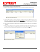
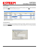
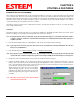
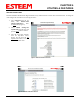
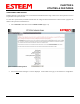
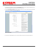
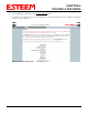
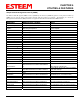
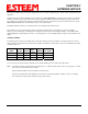
Table Of Contents
- Chapter 0 - Front Cover 195CM
- Chapter 0 - Table of Contents 195CM
- CHAPTER 1 – Introduction
- Before You Begin
- Model 195C/M Overview
- Three Configuration Phases
- Model 195C/M Hardware Description
- Modes of Operation Description and Examples
- Programming Examples
- CHAPTER 5 – Web Configuration
- Logging Into Web Configuration Manager
- Web Configuration Manager
- CHAPTER 6 – Serial Configuration and Applications
- Using USB Programming Port
- Using RS-232 Data Port
- ESTeem Mesh Network
- Rapid Spanning Tree Protocol (RSTP)
- Spanning Tree Protocols (STP)
- Redundant Backup
- CHAPTER 8 – Antenna Setups
- Antenna and Cable Configurations
- Weatherproofing Coaxial Cable Connections
- APPENDIX A – FCC Information
- APPENDIX B – Interface Ports
- APPENDIX C – Radio Configuration
- APPENDIX E – Troubleshooting
- APPENDIX F – 195C/M Specifications
- CHAPTER 1 – Introduction
- Chapter 1 - Introduction 195CM
- BEFORE YOU BEGIN
- MODEL 195C/M OVERVIEW
- The ESTeem Model 195C and 195M are wireless modem transceivers that can be used to build many types of Wireless Local Area Networks (WLAN). The ESTeem 195C/M series have multiple serial (RS-232, RS-422 and RS-485), Ethernet and 4/20mA sensor interfaces. The Model 195C and 195M can be configured for multiple modes of operation depending upon the needs of the wireless and wired network. The following interface configurations are provided as an overview of the basic network types, as all possible network configurations can not be listed. For further help in selecting the correct network type, please refer to Chapter 3 of this User’s Manual or call Customer Support at 509-735-9092.
- SERIAL APPLICATIONS
- ETHERNET APPLICATIONS
- Chapter 2 - Starting Out 195CM
- Chapter 3 - Example Applications 195CM
- Chapter 4 - Repeating 195CM
- Chapter 5 - Ethernet Configuration and Applications 195CM
- Chapter 6 - Utilities and Features 195CM
- ESTeem Network Configuration Utility (ENC)
- Note: The ESTeem Resource Disk is a stand-alone copy of the ESTeem Web site (Figure 2). Navigation of the Resource Disk is as simple as using your web browser. All technical documentation, User’s Manuals and the ESTeem Utility Program are available on the disk.
- Note: If the page does not auto load, open your web browser and set your address line to D:\index.html (Where D: is the drive letter for your CD-ROM drive).
- Note: This program is saved in a compressed file format.
- Note: The SSID, Mode of Operation and Modem ID will be adjusted through the ENC Utility or the Web Configuration Manager...
- Note: The ESTeem Resource Disk is a stand-alone copy of the ESTeem Web site (Figure 1). Navigation of the Resource Disk is as simple as using your web browser. All technical documentation, User’s Manuals and the ESTeem Utility Program are available on the disk.
- Note: If the page does not auto load, open your web browser and set your address line to D:\index.html (Where D: is the drive letter for your CD-ROM drive).
- Note: This program is saved in a compressed file format. Microsoft Windows XP® will open the file directly, but other operating systems will require a common compression program such as WinZip available for download at http://www.winzip.com
- Note: This Utility will only operate with an ESTeem Model 195C/M in EtherStation mode.
- Chapter 7 - Antenna Setup 195CM
- Apx A - Software Commands 195CM
- Apx B - Interface Ports 195CM
- Apx C - Model 192 Integration 195CM
- Apx D - FCC Information 195CM
- Apx E - 195C Specifications
- Apx F - 195M Specifications

CHAPTER 7
ANTENNA SETUPS
Revised: 24 Jan 14 7-1 EST P/N AA107-195CM
ESTeem offers different types of antennas ranging from ¼ wave to 5/8 wave in physical size. The user choice is dependent on the
application.
Communications in the VHF and UHF bands are normally over "Line of Sight (LOS)". Looking from the antenna of one wireless
modem you must be able to see the antenna of the wireless modem you wish to communicate with. If a large object obstructs the
line of sight view it is unlikely that satisfactory communications will result. This means you must relocate the antennas or use the
REPEATER FEATURE and a second modem to go over or around the object.
The Model 195C/MC products are allowed by the FCC to use high gain directional antennas.
It is noted that a ¼ wave antenna that does not have ground plane radials requires a ground plane to operate at maximum
efficiency. This can simply be a conducting surface under the antenna that is a ¼ wavelength in diameter. For the Model 195C
(450-470 MHz) this is approximately 6.5 inches. A conducting surface can be anything from the rooftop of an automobile to a file
cabinet.
COAXIAL CABLES
To minimize signal loss, the overall length of the coaxial cable should be as short as possible. To avoid corrosion select coaxial
cable manufacturers with tinned copper braid, where possible. Listed below are representative cable losses in db/100ft at the VHF
and UHF frequencies:
Frequency
(MHz)
RG-58u
LMR 195
RG-8
(solid)
LMR600
1/2" Heliax
150-174 -5.2 -4.4 -1.7 -0.964 -0.88
402-420 -8.4 -7.8 -2.9 -1.72 -1.36
450-470 -9 -7.8 -3 -1.72 -1.45
In a severe noise environment it may be desirable to use a double shield type of coax cable such as RG-214/U.
Note: Pre-made coax cables can be purchased from the factory. A -3 dB loss means you have lost 1/2 of your signal. A +3 dB
gain means you have doubled (x2) your signal.
Keep the antenna feedline as short as possible to minimize losses.
Extreme care must be taken when attaching coax connectors to the antenna feedlines. If there is any error in making
this connection the output of the transmitter will be greatly reduced.