
User's Manual
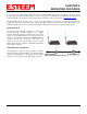
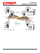
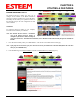
Table Of Contents
- Chapter 0 - Front Cover 195CM
- Chapter 0 - Table of Contents 195CM
- CHAPTER 1 – Introduction
- Before You Begin
- Model 195C/M Overview
- Three Configuration Phases
- Model 195C/M Hardware Description
- Modes of Operation Description and Examples
- Programming Examples
- CHAPTER 5 – Web Configuration
- Logging Into Web Configuration Manager
- Web Configuration Manager
- CHAPTER 6 – Serial Configuration and Applications
- Using USB Programming Port
- Using RS-232 Data Port
- ESTeem Mesh Network
- Rapid Spanning Tree Protocol (RSTP)
- Spanning Tree Protocols (STP)
- Redundant Backup
- CHAPTER 8 – Antenna Setups
- Antenna and Cable Configurations
- Weatherproofing Coaxial Cable Connections
- APPENDIX A – FCC Information
- APPENDIX B – Interface Ports
- APPENDIX C – Radio Configuration
- APPENDIX E – Troubleshooting
- APPENDIX F – 195C/M Specifications
- CHAPTER 1 – Introduction
- Chapter 1 - Introduction 195CM
- BEFORE YOU BEGIN
- MODEL 195C/M OVERVIEW
- The ESTeem Model 195C and 195M are wireless modem transceivers that can be used to build many types of Wireless Local Area Networks (WLAN). The ESTeem 195C/M series have multiple serial (RS-232, RS-422 and RS-485), Ethernet and 4/20mA sensor interfaces. The Model 195C and 195M can be configured for multiple modes of operation depending upon the needs of the wireless and wired network. The following interface configurations are provided as an overview of the basic network types, as all possible network configurations can not be listed. For further help in selecting the correct network type, please refer to Chapter 3 of this User’s Manual or call Customer Support at 509-735-9092.
- SERIAL APPLICATIONS
- ETHERNET APPLICATIONS
- Chapter 2 - Starting Out 195CM
- Chapter 3 - Example Applications 195CM
- Chapter 4 - Repeating 195CM
- Chapter 5 - Ethernet Configuration and Applications 195CM
- Chapter 6 - Utilities and Features 195CM
- ESTeem Network Configuration Utility (ENC)
- Note: The ESTeem Resource Disk is a stand-alone copy of the ESTeem Web site (Figure 2). Navigation of the Resource Disk is as simple as using your web browser. All technical documentation, User’s Manuals and the ESTeem Utility Program are available on the disk.
- Note: If the page does not auto load, open your web browser and set your address line to D:\index.html (Where D: is the drive letter for your CD-ROM drive).
- Note: This program is saved in a compressed file format.
- Note: The SSID, Mode of Operation and Modem ID will be adjusted through the ENC Utility or the Web Configuration Manager...
- Note: The ESTeem Resource Disk is a stand-alone copy of the ESTeem Web site (Figure 1). Navigation of the Resource Disk is as simple as using your web browser. All technical documentation, User’s Manuals and the ESTeem Utility Program are available on the disk.
- Note: If the page does not auto load, open your web browser and set your address line to D:\index.html (Where D: is the drive letter for your CD-ROM drive).
- Note: This program is saved in a compressed file format. Microsoft Windows XP® will open the file directly, but other operating systems will require a common compression program such as WinZip available for download at http://www.winzip.com
- Note: This Utility will only operate with an ESTeem Model 195C/M in EtherStation mode.
- Chapter 7 - Antenna Setup 195CM
- Apx A - Software Commands 195CM
- Apx B - Interface Ports 195CM
- Apx C - Model 192 Integration 195CM
- Apx D - FCC Information 195CM
- Apx E - 195C Specifications
- Apx F - 195M Specifications

CHAPTER 5
ETHERNET APPLICATIONS
Revised: 24 Jan 14 5-5 EST P/N AA107-195CM
Flow Control
Select the type of data flow control used on the RS-232 connection. The ESTeem can support Hardware flow control (RTS/CTS
control lines) or Software Flow Control (XON/XOFF). Select None
if no serial flow control is necessary.
Maximum Bridge Links for Multicast Packets
This value sets the maximum number of Ethernet bridge links that the multicast packets will be sent through when used in a multi-
point system. A multi-point serial network uses multicast packets (UDP) to send the data to more than one remote ESTeem. You
want to limit the number of network bridge links that these UDP packets will be passed through to make the network more
efficient.
If you are using multiple ESTeem repeater links to send the serial data to remote locations, the value for the maximum bridge link
needs to be increased to a number greater than the longest repeater chain. For example, if you are using four repeater (peer) links
to send the serial data between two or more sites the number will need to be five (5) or greater (Figure 4).
Destination IP Address
The ESTeem configured for the correct destination IP and port number will send and receive the serial data from another modem.
Set the destination IP address for the ESTeem where the serial data will be sent. If sending to more than one ESTeem (Multipoint)
set to a multicast address (i.e 224.0.0.1).
Note: If you are using the ESTeem 195C/M in a multipoint application (multicast), you must have default Gateway configured
in the ESTeem set to the IP address of the Root Bridge modem.
Serial IP Port Number
The ESTeem configured for the correct destination IP and port number will send and receive the serial data from another modem.
Set the IP port numbers to match where the serial data will be sent. The serial data will not be sent if both the IP address and port
number is not correct.
Maximum Packet Size
This number represents the maximum size of the serial data packet in bytes. If the number of bytes of data in the serial port buffer
exceeds the maximum packet size
before the timer or delimiter character is reached, the ESTeem will send forward the serial
packet. For example, if the maximum packet size
is set to a value of 100, when the serial port receives 100 bytes the data will be
sent through the wireless connection.
Number of Milliseconds for Packetization
This number represents the time the ESTeem will hold data in the serial data buffer before sending to the remote ESTeem. This
feature is generally used if the serial data does not have a consistent packet length or delimiter character. For example, if the
number of milliseconds is set to a value of 10 the ESTeem will monitor the incoming serial data stream and any break in characters
longer than 10 milliseconds will cause the data will be sent through the wireless connection.
Delimiter Characters
Enabling and specifying a delimiter character will transmit the data in the serial buffer when the delimiter character is recognized
in the serial data stream. There are two unique delimiter characters that can be configured and enabled independently.
Terminal Server Control Lines
Enabling this feature will allow the ESTeem in the Terminal Server mode to read and generate modem control lines to the
connected device.