
User's Manual
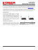

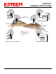
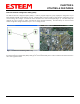

Table Of Contents
- Chapter 0 - Front Cover 195CM
- Chapter 0 - Table of Contents 195CM
- CHAPTER 1 – Introduction
- Before You Begin
- Model 195C/M Overview
- Three Configuration Phases
- Model 195C/M Hardware Description
- Modes of Operation Description and Examples
- Programming Examples
- CHAPTER 5 – Web Configuration
- Logging Into Web Configuration Manager
- Web Configuration Manager
- CHAPTER 6 – Serial Configuration and Applications
- Using USB Programming Port
- Using RS-232 Data Port
- ESTeem Mesh Network
- Rapid Spanning Tree Protocol (RSTP)
- Spanning Tree Protocols (STP)
- Redundant Backup
- CHAPTER 8 – Antenna Setups
- Antenna and Cable Configurations
- Weatherproofing Coaxial Cable Connections
- APPENDIX A – FCC Information
- APPENDIX B – Interface Ports
- APPENDIX C – Radio Configuration
- APPENDIX E – Troubleshooting
- APPENDIX F – 195C/M Specifications
- CHAPTER 1 – Introduction
- Chapter 1 - Introduction 195CM
- BEFORE YOU BEGIN
- MODEL 195C/M OVERVIEW
- The ESTeem Model 195C and 195M are wireless modem transceivers that can be used to build many types of Wireless Local Area Networks (WLAN). The ESTeem 195C/M series have multiple serial (RS-232, RS-422 and RS-485), Ethernet and 4/20mA sensor interfaces. The Model 195C and 195M can be configured for multiple modes of operation depending upon the needs of the wireless and wired network. The following interface configurations are provided as an overview of the basic network types, as all possible network configurations can not be listed. For further help in selecting the correct network type, please refer to Chapter 3 of this User’s Manual or call Customer Support at 509-735-9092.
- SERIAL APPLICATIONS
- ETHERNET APPLICATIONS
- Chapter 2 - Starting Out 195CM
- Chapter 3 - Example Applications 195CM
- Chapter 4 - Repeating 195CM
- Chapter 5 - Ethernet Configuration and Applications 195CM
- Chapter 6 - Utilities and Features 195CM
- ESTeem Network Configuration Utility (ENC)
- Note: The ESTeem Resource Disk is a stand-alone copy of the ESTeem Web site (Figure 2). Navigation of the Resource Disk is as simple as using your web browser. All technical documentation, User’s Manuals and the ESTeem Utility Program are available on the disk.
- Note: If the page does not auto load, open your web browser and set your address line to D:\index.html (Where D: is the drive letter for your CD-ROM drive).
- Note: This program is saved in a compressed file format.
- Note: The SSID, Mode of Operation and Modem ID will be adjusted through the ENC Utility or the Web Configuration Manager...
- Note: The ESTeem Resource Disk is a stand-alone copy of the ESTeem Web site (Figure 1). Navigation of the Resource Disk is as simple as using your web browser. All technical documentation, User’s Manuals and the ESTeem Utility Program are available on the disk.
- Note: If the page does not auto load, open your web browser and set your address line to D:\index.html (Where D: is the drive letter for your CD-ROM drive).
- Note: This program is saved in a compressed file format. Microsoft Windows XP® will open the file directly, but other operating systems will require a common compression program such as WinZip available for download at http://www.winzip.com
- Note: This Utility will only operate with an ESTeem Model 195C/M in EtherStation mode.
- Chapter 7 - Antenna Setup 195CM
- Apx A - Software Commands 195CM
- Apx B - Interface Ports 195CM
- Apx C - Model 192 Integration 195CM
- Apx D - FCC Information 195CM
- Apx E - 195C Specifications
- Apx F - 195M Specifications

CHAPTER 4
REPEATING FEATURES
Revised: 24 Jan 14 4-4 EST P/N AA107-195CM
determine routing and which paths will be blocked. On a wired Ethernet network, the location of the Root Bridge is not really
important, but in a wireless network selection of the Root Bridge is critical to the wireless network routing. Let’s use one of the
Example network diagrams from Chapter 3 to continue the discussion (Figure 4).
STP Phases
The following sections describe the process of the STP in the ESTeem Model 195C/M as how it would happen in the above
example.
Learning Phase
- Once properly configured, each Model 195C/M will begin to search out the other Model 195C/M units in radio
range that are programmed in the AP Repeater Peer table. All Model 195C/M’s will calculate their routes to every Model 195C/M
in the network based upon the lowest “path length” to the Root Bridge. Path length is the total number of wireless links (repeater
peer links) to transmit a packet through the wireless network to the Root Bridge. Note: The Root Bridge in a network should be
the Model 195C/M where the majority of the data flow is processed. In every wireless network of two or more radios, the Root
Bridge should be user defined. If not defined, the ESTeem 195C/M with the lowest MAC address will be designated as the Root
Bridge.
In Figure 4, the Plant network (Example 1) is the most logical location for the Root Bridge based upon the amount of data flow.
Setting this site as the root bridge is discussed below in Root Bridge.
Blocking and Forwarding Phase
– To ensure you do not have a network loop situation due to redundant paths in your wireless
network, the Model 195C/M will recognize and disable (block) one or more redundant links and provide back up links should the
primary link fail. This establishes a wireless mesh network with a series of forwarding links, based upon the shortest path length to
the Root Bridge.
For example, looking at Figure 4, the Remote Building has two routes to the Root Bridge (Plant Network – Example #1); directly
to the site and through the repeater. The direct link between the two sites is the shortest route (lowest Path Length) and will be
selected as the primary route unless overridden by manually changing the Path Length in the configuration.
Path Length
If more than one communication path to the Root Bridge is found, the 195C/M must determine which route to take based upon the
lowest Path Length. The default path length to all links in the 195C/M network is 1. If the Path Lengths are equal then the lowest
MAC address will determine the priority route. In the ESTeem Mesh Network we want to directly control all data flow so do not
want the routes to be automatically determined.
Looking again at our Example in Figure 4, if we made no changes to the default path length of 1 (note values in Figure 3) the
lowest path cost would be direct from the Remote Building to the Root Bridge (Plant Network).
Link Description Total Path Length
Direct from Remote Building 1
Remote Build to Root Bridge Through
Repeater
2
(Length 1 to repeater + Length 1 to Master = 2)
To configure the 195C/M to select the repeater as the primary radio path, set the path length value for the direct link greater than 2
(such as a value of 3) to make this the primary radio path. The lowest path length will identify the highest priority. The Model
195C/M will use this routing, but also switch to direct communication if the repeater were to disappear.
Root Bridge
In any
Access Point Repeater network consisting of more than two sites, one Model 195C/M should be designated as the Root
Bridge. Only one Model 195C/M can be designated as the Root Bridge in a given network and should be located where the
majority of the Ethernet data flow is processed. This site may be the Master location in a SCADA network or could be configured