
User's Manual
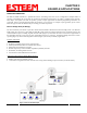
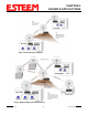
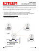
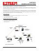
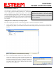
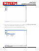
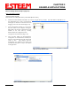
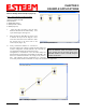
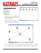
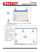
Table Of Contents
- Chapter 0 - Front Cover 195CM
- Chapter 0 - Table of Contents 195CM
- CHAPTER 1 – Introduction
- Before You Begin
- Model 195C/M Overview
- Three Configuration Phases
- Model 195C/M Hardware Description
- Modes of Operation Description and Examples
- Programming Examples
- CHAPTER 5 – Web Configuration
- Logging Into Web Configuration Manager
- Web Configuration Manager
- CHAPTER 6 – Serial Configuration and Applications
- Using USB Programming Port
- Using RS-232 Data Port
- ESTeem Mesh Network
- Rapid Spanning Tree Protocol (RSTP)
- Spanning Tree Protocols (STP)
- Redundant Backup
- CHAPTER 8 – Antenna Setups
- Antenna and Cable Configurations
- Weatherproofing Coaxial Cable Connections
- APPENDIX A – FCC Information
- APPENDIX B – Interface Ports
- APPENDIX C – Radio Configuration
- APPENDIX E – Troubleshooting
- APPENDIX F – 195C/M Specifications
- CHAPTER 1 – Introduction
- Chapter 1 - Introduction 195CM
- BEFORE YOU BEGIN
- MODEL 195C/M OVERVIEW
- The ESTeem Model 195C and 195M are wireless modem transceivers that can be used to build many types of Wireless Local Area Networks (WLAN). The ESTeem 195C/M series have multiple serial (RS-232, RS-422 and RS-485), Ethernet and 4/20mA sensor interfaces. The Model 195C and 195M can be configured for multiple modes of operation depending upon the needs of the wireless and wired network. The following interface configurations are provided as an overview of the basic network types, as all possible network configurations can not be listed. For further help in selecting the correct network type, please refer to Chapter 3 of this User’s Manual or call Customer Support at 509-735-9092.
- SERIAL APPLICATIONS
- ETHERNET APPLICATIONS
- Chapter 2 - Starting Out 195CM
- Chapter 3 - Example Applications 195CM
- Chapter 4 - Repeating 195CM
- Chapter 5 - Ethernet Configuration and Applications 195CM
- Chapter 6 - Utilities and Features 195CM
- ESTeem Network Configuration Utility (ENC)
- Note: The ESTeem Resource Disk is a stand-alone copy of the ESTeem Web site (Figure 2). Navigation of the Resource Disk is as simple as using your web browser. All technical documentation, User’s Manuals and the ESTeem Utility Program are available on the disk.
- Note: If the page does not auto load, open your web browser and set your address line to D:\index.html (Where D: is the drive letter for your CD-ROM drive).
- Note: This program is saved in a compressed file format.
- Note: The SSID, Mode of Operation and Modem ID will be adjusted through the ENC Utility or the Web Configuration Manager...
- Note: The ESTeem Resource Disk is a stand-alone copy of the ESTeem Web site (Figure 1). Navigation of the Resource Disk is as simple as using your web browser. All technical documentation, User’s Manuals and the ESTeem Utility Program are available on the disk.
- Note: If the page does not auto load, open your web browser and set your address line to D:\index.html (Where D: is the drive letter for your CD-ROM drive).
- Note: This program is saved in a compressed file format. Microsoft Windows XP® will open the file directly, but other operating systems will require a common compression program such as WinZip available for download at http://www.winzip.com
- Note: This Utility will only operate with an ESTeem Model 195C/M in EtherStation mode.
- Chapter 7 - Antenna Setup 195CM
- Apx A - Software Commands 195CM
- Apx B - Interface Ports 195CM
- Apx C - Model 192 Integration 195CM
- Apx D - FCC Information 195CM
- Apx E - 195C Specifications
- Apx F - 195M Specifications

CHAPTER 3
EXAMPLE APPLICATIONS
in the repeater Mesh configuration (Figure 17). For detailed instruction on Mesh network configuration, refer to Chapter
7 of this User’s Manual.
Figure 16: Backup Link Configuration
4. Verify
all ESTeem modems are
connected to the same switch as
the computer running the ENC
Utility and send the configuration
to all modems at the same time
by selecting ESTeem>ESTeem
Configuration>Send
Configuration to All ESTeems.
Once the ENC Utility has
downloaded the configuration for
both ESTeem 195C/M’s, the
status box around the ESTeem‘s
will change from yellow to blue.
This indicates that the
configuration was completed
successfully and the ESTeem
195C/M’s are ready to be
installed in the application.
Figure 17: Mesh Network Configuration
Revised: 24 Jan 14 3-10 EST P/N AA107-195CM