
User's Manual
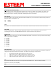
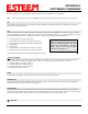
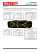
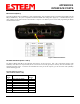
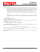
Table Of Contents
- Front Cover 195CM
- Table of Contents 195CM
- Chapter 1 - Introduction 195CM
- Chapter 2 - Starting Out 195CM
- Chapter 3 - Example Applications 195CM
- Chapter 4 - Repeating 195CM
- Chapter 5 - Ethernet Configuration and Applications 195CM
- Chapter 6 - Utilities and Features 195CM
- Chapter 7 - Antenna Setup 195CM
- Apx A - Software Commands 195CM
- Apx B - Interface Ports 195CM
- Apx C - Model 192 Integration 195CM
- Apx D - FCC Information
- Apx E - 195C Specifications
- Apx F - 195M Specifications

APPENDIX C
MODEL 192 INTEGRATION
Revised: 4 Feb 14 APX C-1 EST P/N AA107-195CM
Model Series 192 Integration
The ESTeem Model 195C and 195M were designed to be downward compatible
with the legacy ESTeem Model 192 series of wireless modems. The Model 192
series had been in production since 1996 with several generational changes in the
product lifespan. The manufacturing variations throughout this time require that a
new ESTeem Model 195C/M be “trained” to communicate with an existing Model
192 network. This training process (described below) will allow the Model
195C/M to recognize any change in deviation in the older radios and adjust accordingly.
Technical Tip: The ESTeem Model
192 network MUST be configured for
narrow band (12.5 kHz) operation
before Model 195C/M integration.
If an ESTeem
195C/M is added to an existing Model
192 network, it is highly
recommended the Model
195C/M is installed at a remote location and not the
Master or Repeater location of the Model 192
network (Figure 1). If the 195C/M is required to be
used as the Master or Repeater site, “train” the radio
modem to one of the remote locations and then test all
wireless links from that location.
The Model 195C/M configuration utility can be used
to provide local signal strength (RSSI) information
but can not gather information from a Model 192
because the process uses ModbusTCP protocol only
available in the 195C/M. The ESTeem Model 192
configuration utility’s diagnostic can be used to test
the operation of the wireless network but must be run
from the Model 192 side of the wireless network. For
example in Figure 1, the diagnostic utility (Polling
Test) must be run from the Master SCADA location.
Figure 1: Model 192 Integration Diagram
Configuring Model 195C/195M for Model 192
The ESTeem Model 195C and 195M must be “trained” to
communicate with an ESTeem Model 192. The training
completed using the 195 Series Narrow Band Configuration
Utility and selecting the “192 Compatibility” tab. Select Remote
and enter the remote address of the ESTeem Model 192 in the
utility and press the Train to Remote button (Figure 2). The
Model 195C/M will begin training to the remote ESTeem and
will save the configuration once complete (Figure 2). Verify the
communication using both the 195C/M and Model 192
configuration utilities.
Figure 2: Training Model 195C/M