
User's Manual
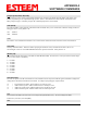
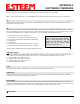
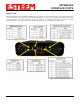
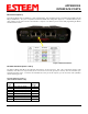
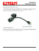
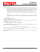
Table Of Contents
- Front Cover 195CM
- Table of Contents 195CM
- Chapter 1 - Introduction 195CM
- Chapter 2 - Starting Out 195CM
- Chapter 3 - Example Applications 195CM
- Chapter 4 - Repeating 195CM
- Chapter 5 - Ethernet Configuration and Applications 195CM
- Chapter 6 - Utilities and Features 195CM
- Chapter 7 - Antenna Setup 195CM
- Apx A - Software Commands 195CM
- Apx B - Interface Ports 195CM
- Apx C - Model 192 Integration 195CM
- Apx D - FCC Information
- Apx E - 195C Specifications
- Apx F - 195M Specifications

APPENDIX B
INTERFACE PORTS
Revised: 4 Feb 14 APX B-3 EST P/N AA107-195CM
RS-485 and RS-422 Data Ports (Ports 1 and 2)
The ESTeem Model 195C/M have a single, two-wire RS-485 interface in Port 1 and a single, four-wire RS-422 interface in Port 2.
To ease access to these ports the AA066 (Figure 3) cable adapter is available. The RJ-45 interface can be inserted into either Port
1 (RS-485) or Port 2 (RS-422) and the corresponding signal lines (Figure 1) can be inserted in the screw terminals.
Note: Verify the screw terminal cover is attached to the cable before termination.
4/20mA Sensor Inputs (Port 1)
Figure 3: AA066 Cable Adapter
The ESTeem
Model 195C/M have four independent 4/20mA inputs sensors that can be read through either ModbusTCP protocol
(See Chapter 6) or through the “sread” software command from a serial port. For detailed information on scaling or modifications
to sensor reading, please contact ESTeem customer support at 509-735-9092.