
User's Manual
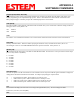
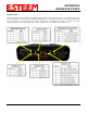
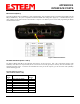
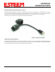
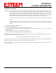
Table Of Contents
- Front Cover 195CM
- Table of Contents 195CM
- Chapter 1 - Introduction 195CM
- Chapter 2 - Starting Out 195CM
- Chapter 3 - Example Applications 195CM
- Chapter 4 - Repeating 195CM
- Chapter 5 - Ethernet Configuration and Applications 195CM
- Chapter 6 - Utilities and Features 195CM
- Chapter 7 - Antenna Setup 195CM
- Apx A - Software Commands 195CM
- Apx B - Interface Ports 195CM
- Apx C - Model 192 Integration 195CM
- Apx D - FCC Information
- Apx E - 195C Specifications
- Apx F - 195M Specifications

APPENDIX B
INTERFACE PORTS
Revised: 4 Feb 14 APX B-2 EST P/N AA107-195CM
Ethernet Port (Port 2)
The ESTeem Model 195C and 195M have a Full and Half-Duplex Auto-negotiation interface supporting both 10 Mbps and 100
Mbps (10/100BaseT). The port is compatible with TIA/EIA-568B cable configuration (Figure 2). A standard Ethernet patch
cable (AA09.2) can be used to interface the 195C/M to a computer. The Ethernet port is used for both programming the Model
195C/M and data transfer.
Figure 2: Ethernet Interface
RS-232C Data Ports (Ports 3 and 4)
The ESTeem Model 195C/M has two RS-232C data interfaces on the front panel. Port 3 has a full RS-232 interface with
handshake, while Port 4 has only Transmit, Receive and Ground. Port 4 will generally be used only when the 195C/M is pole
mounted with remote power. To interface the 195C/M to the serial port on the computer, you will need serial cable (AA0621)
with the following pin-out:
ESTeem Model 195C/M Port 3
(ESTeem Model AA0621 Cable)
RJ-45
Pin No.
Function
DB-9
Pin No.
1
Data Set Ready (DSR)
6
2
Data Carrier Detect (DCD)
1
3
Data Terminal Ready (DTR)
4
4
Signal Ground (GND)
5
5
Receive Data (RxD)
2
6
Transmit Data (TxD)
3
7
Clear to Sent (CTS)
8
8
Request to Sent (RTS)
7