
User's Manual
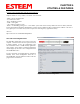
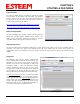
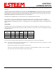
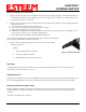
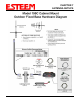


Table Of Contents
- Front Cover 195CM
- Table of Contents 195CM
- Chapter 1 - Introduction 195CM
- Chapter 2 - Starting Out 195CM
- Chapter 3 - Example Applications 195CM
- Chapter 4 - Repeating 195CM
- Chapter 5 - Ethernet Configuration and Applications 195CM
- Chapter 6 - Utilities and Features 195CM
- Chapter 7 - Antenna Setup 195CM
- Apx A - Software Commands 195CM
- Apx B - Interface Ports 195CM
- Apx C - Model 192 Integration 195CM
- Apx D - FCC Information
- Apx E - 195C Specifications
- Apx F - 195M Specifications

APPENDIX A
SOFTWARE COMMANDS
Revised: 4 Feb 14 APX A-1 EST P/N AA107-195CM
Listed below in alphabetical order are the definitions of the ESTeem software commands. All software commands are entered
lowercase. The commands are displayed below with the full software command and the shorted command underlined.
? or help
help Displays the modem information and sub help menus.
help all Displays all commands switches and arguments.
help change Displays only the commands that are changed from factory default.
help control Displays control commands switches and arguments.
help plc Displays plc commands switches and arguments.
help radio Displays radio commands switches and arguments.
help interface Displays interface commands switches and arguments.
help setup Displays setup commands switches and arguments.
help system Displays system commands switches and arguments.
help 192compat Display commands for 192 compatibility
a_bctrl (1-4)
This function selects the Rockwell Automation (Allen-Bradley) DF1 controller protocol. Full emulation is enabled with the PLC
Protocol (plcproto) software command
1 = Full Duplex DF1 with CRC Error Checking
2 = Full Duplex DF1 with BCC Error Checking
3 = Half Duplex DF1 with CRC Error Checking
4 = Half Duplex DF1 with BCC Error Checking
Factory default = 1.
address (1-255)
The command defines the ESTeem source address. The default value is the last octet of the stored IP address. For example is the
IP address of the ESTeem 195C/M is 172.16.10.184, the address of the modem would be 184. Addresses 1 to 254 are usable for
unit addressing. Address 255 is used for GLOBAL.
appendroute (l#,r#,a1,a2,g)
The append
route command appends routes to a connect address that are defined by the ROUTE command.
l # = Location of route number in memory. Address locations 1 to 32.
r # = Appended route number. Route numbers 1 to 32.
a1 = Address of first destination node. Address numbers from 1 to 254.
a2 = Address of last destination node. . Address numbers from 1 to 254.
g = Group feature is enabled by inserting a 1 in this field.
Factory default = 0. APPEndru 0 disables this feature.
Note: This command is used in conjunction with the ROUTE Command.
arpproxy (on/off)
The arpproxy command enables the ARP Proxy for Ethernet communications. See Chapter 5 for full details on Ethernet
communication. Factory default = off
on = Enabled.
off = Disabled.
baud (2400-115000)