
User's Manual
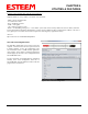
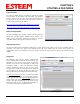
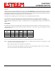
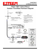
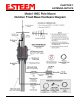
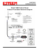
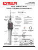
Table Of Contents
- Front Cover 195CM
- Table of Contents 195CM
- Chapter 1 - Introduction 195CM
- Chapter 2 - Starting Out 195CM
- Chapter 3 - Example Applications 195CM
- Chapter 4 - Repeating 195CM
- Chapter 5 - Ethernet Configuration and Applications 195CM
- Chapter 6 - Utilities and Features 195CM
- Chapter 7 - Antenna Setup 195CM
- Apx A - Software Commands 195CM
- Apx B - Interface Ports 195CM
- Apx C - Model 192 Integration 195CM
- Apx D - FCC Information
- Apx E - 195C Specifications
- Apx F - 195M Specifications

CHAPTER 6
UTILITIES & FEATURES
Update Firmware
Revised: 7 Feb 14 6-6 EST P/N AA107-195CM
The
195C
and 195M firmware is updated by pressing the Update
Firmware button on the Firmware tab of the utility. The firmware
version is tied to the release version of the utility and is listed below
the address (Figure 10). The release of any new firmware version will
be listed on the products web site address:
http://www.esteem.com/products/195c-450-470-mhz-serial.html
http://www.esteem.com/products/195m-150-174-mhz-serial.html
Model 192 Compatibility
The 195C and 195M require “training” to operate with legacy ESTeem
Model 192C, 192CHP, 192M or 192MHP wireless modems. The
training process and network installation procedures are found in
Appendix C (Model 192 Integration) of this User’s Manual.
Figure 9: Save and Load Configuration
Programming Console
The 195 Series Narrow Band Configuration
Utility
has a console window to allow direct access to enter and modify software
commands. The console uses Telnet to the 195C/M and will link to the modem when the Console tab is selected. If
communication is lost to the modem (on reset) you may have to press the Connect button to again see the command prompt
(CMD:).
Diagnostics
The diagnostic menu tests the wireless communication
between multiple ESTeem 195C/M wireless modems. The
diagnostic tab will test the receive signal strength both
directions in the wireless link and display the data packet
transmission statistics. Enter the destination ESTeem
addresses separated by commas or you can enter a range
(example 5-10 is all addresses 5 through 10) in the “Radios to
Test” box (Figure 10). Pressing the Start Tests button once
will begin the testing and pressing again will stop the testing.
The
General Activity Log
will show the instantaneous results
of the testing such as which site is being polled and the
current signal strength. The Signal Strength
tab will show a
running graph of all receive signal strengths (both local and
remote). The signal strength graph can be copied, saved or
printed for further analysis. All diagnostic information can
be saved by pressing the Generate Reports button.
Figure 10: Save and Load Configuration