
User's Manual
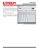
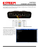
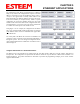

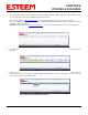
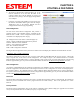
Table Of Contents
- Front Cover 195CM
- Table of Contents 195CM
- Chapter 1 - Introduction 195CM
- Chapter 2 - Starting Out 195CM
- Chapter 3 - Example Applications 195CM
- Chapter 4 - Repeating 195CM
- Chapter 5 - Ethernet Configuration and Applications 195CM
- Chapter 6 - Utilities and Features 195CM
- Chapter 7 - Antenna Setup 195CM
- Apx A - Software Commands 195CM
- Apx B - Interface Ports 195CM
- Apx C - Model 192 Integration 195CM
- Apx D - FCC Information
- Apx E - 195C Specifications
- Apx F - 195M Specifications

CHAPTER 6
UTILITIES & FEATURES
Modbus Monitoring
Revised: 7 Feb 14 6-4 EST P/N AA107-195CM
The ESTeem
195C
/M support ModbusTCP protocol for
access to multiple operating parameters in the wireless
modem. Receive signal strengths, background noise,
input voltage, and packet transmissions are a few of the
parameter available though the open ModbusTCP
protocol. There are multiple methods for extracting the
data from the 195C/M, but the Configuration Utility has
simple data interface on the Configuration Tab. Pressing
the Modbus Monitoring button once will start the data
monitor of either the local ESTeem 195C/M or the
remote defined in the Route/Append tab (Figure 7).
Note: For remote Modbus Monitoring, the route to the
remote locations MUST be defined in the Route and
Append tables. See Chapters 4 and 5 for routing
configuration.
The 195 Narrowband Configuration Utility will update
the current status of the operating parameters until the
Modbus Monitoring button is pressed a second time. If
multiple repeaters are required to access a remote or the
Modbus monitoring is used on a busy network, the
Modbus Timeout parameter may need to be adjusted.
Figure 7: Modbus Monitoring Screen
The
fol
lowing are the Modbus registers supported in the ESTeem 195C and 195M on Port 502. Registers are mapped as 32-bit
floating point numbers (2 registers each):
1000 (4-20 mA channel 1)
1002 (4-20 mA channel 2)
1004 (4-20 mA channel 3)
1006 (4-20 mA channel 4)
1008 (MCU temperature in F)
1010 (Auxiliary voltage - 0 if not connected)
1012 (Instantaneous RSSI dBm from non-ESTeem 192/195 radios)
1014 (Radio uptime in seconds)
1016 (Total RX bytes received)
1018 (Total TX bytes sent)
1020 (Number of header blocks / short packets (UA, SABM, etc) received)
1022 (Number of long packets received (> 1 block))
1024 (Number of transmitted packets)
1026 (Number of failed error correction on headers)
1028 (Number of failed error correction on data)
1030 (Number of re-transmits (if retries and acks enabled))
1032 (Average noise floor in dBm)
1034 (Power level of last valid packet received from ESTeem 192/195)
1036 (0/1 Ethernet link up/down)
1038 (Model Serial Number)