
User's Manual


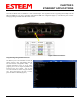
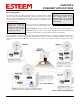


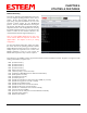
Table Of Contents
- Front Cover 195CM
- Table of Contents 195CM
- Chapter 1 - Introduction 195CM
- Chapter 2 - Starting Out 195CM
- Chapter 3 - Example Applications 195CM
- Chapter 4 - Repeating 195CM
- Chapter 5 - Ethernet Configuration and Applications 195CM
- Chapter 6 - Utilities and Features 195CM
- Chapter 7 - Antenna Setup 195CM
- Apx A - Software Commands 195CM
- Apx B - Interface Ports 195CM
- Apx C - Model 192 Integration 195CM
- Apx D - FCC Information
- Apx E - 195C Specifications
- Apx F - 195M Specifications

CHAPTER 5
ETHERNET APPLICATIONS
The configuration of the Route and Append list for an Ethernet
bridge is very similar to the configuration for repeaters. The main
difference is that the last octet of IP addresses will be used in a
“Group” in the append table to identify which address is the
ESTeem 195C/M. The ESTeem address in the group will always
be the lowest number (see examples below). Unlike a repeater
configuration for serial PLC emulation modes, the return path
from the remote to the master must also be configured in the route
and append tables. If a repeater route is not used to communicate
to a remote site a blank repeater route number is used.
Revised: 4 Feb 14 5-3 EST P/N AA107-195CM
Usi
ng Figure 3 for an example, the configuration of the Master
Site’s route and append table would look like Figure 4. Note that
all
IP addresses in the network are identified in the append table
of the Master Site.
Figure 4: Master Site Configuration
Th
e return paths to the Master site must also be identified in all
remote sites. Figure 5 show the return path entries from Remote 2
through the repeater. The route and append configuration for the
return path from both Remote 1 and Remote 3 will be the same as
shown in Figure 6.
Figure 5: Remote 2 Configuration
Figure 6: Remotes 1 and 3 Configuration
Using the Ethernet Port as a Serial Data Interface
The Ethernet port on the 195C/M can be configured as the serial data interface (SDI) to
be used by software applications to
transport data. The configuration and operation of this mode is outside the scope of this User’s Manual and is available in an
Engineering Report. For specific information on this mode of operation and programming examples, please contact customer
support at 509-735-9092.