
User's Manual
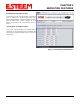
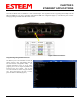
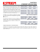

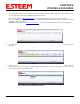
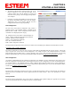
Table Of Contents
- Front Cover 195CM
- Table of Contents 195CM
- Chapter 1 - Introduction 195CM
- Chapter 2 - Starting Out 195CM
- Chapter 3 - Example Applications 195CM
- Chapter 4 - Repeating 195CM
- Chapter 5 - Ethernet Configuration and Applications 195CM
- Chapter 6 - Utilities and Features 195CM
- Chapter 7 - Antenna Setup 195CM
- Apx A - Software Commands 195CM
- Apx B - Interface Ports 195CM
- Apx C - Model 192 Integration 195CM
- Apx D - FCC Information
- Apx E - 195C Specifications
- Apx F - 195M Specifications

CHAPTER 4
REPEATING FEATURES
Revised: 24 Jan 14 4-2 EST P/N AA107-195CM
Route 2: Refer to Figure 1 and find Route 2. This route has
a repeater address of 3 and addresses 20 through 21 use this
route. Note: Although address 20 is a repeater for another
route, it requires an ESTeem address and needs to be
counted. Type 3 in the first repeater block, 20 in the first
address field and 21 in the second (Figure 4).
Figure 4: Route 2 Configuration
Route 3: R
efer to Figure 1, Route 3 and notice there are two
repeaters in this route (addresses 3 and 20). A repeater route
always follows the address path from the master station. The
first repeater address from the master in this route is address
3. Type 3 in the first repeater block. The second repeater
from the master is address 20. Type 20 in the second
repeater block. Addresses 40 through 42 use this route.
Type 40 in the first address field, 42 in the second (Figure 5).
Figure 5: Route 3 Configuration
Route 4: Thi
s fourth route uses a total of three repeaters.
Follow the address route from the master and notice that the
first repeater is address 3. Type 3 in the first repeater block.
The second address from the master in this route is address
20. Type 20 in the second repeater block. The third repeater
address from the master is address 40. Type 40 in the third
repeater block. (Figure 6). Notice that the two addresses that
use this repeater route are not sequential, by putting 30 in the
first block and 35 in the second would allocate addresses 31-
34 to this route. In this example we will input each address
separately. On the first line type 30 in both blocks and on the
second line use the same repeater route number and type 35
in both blocks (Figure 6).
Figure 6: Route 4 Configuration
Once all repeater routes are addressed, press the Write Ta
bles button to save to the connected ESTeem 195C or 195M.