
User's Manual


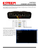
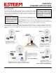


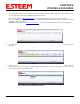
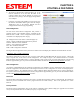
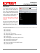
Table Of Contents
- Front Cover 195CM
- Table of Contents 195CM
- Chapter 1 - Introduction 195CM
- Chapter 2 - Starting Out 195CM
- Chapter 3 - Example Applications 195CM
- Chapter 4 - Repeating 195CM
- Chapter 5 - Ethernet Configuration and Applications 195CM
- Chapter 6 - Utilities and Features 195CM
- Chapter 7 - Antenna Setup 195CM
- Apx A - Software Commands 195CM
- Apx B - Interface Ports 195CM
- Apx C - Model 192 Integration 195CM
- Apx D - FCC Information
- Apx E - 195C Specifications
- Apx F - 195M Specifications

CHAPTER 4
REPEATING FEATURES
Revised: 24 Jan 14 4-1 EST P/N AA107-195CM
Any ESTeem Model 195C or 195M in the wireless
network can be used as a repeater to reach a remote
location. Manually entering repeater routes in a terminal
for testing a connection (connect command) or remote
programming (program command) is as simple as adding
the routing in the address with the repeaters identified by
commas. For example using Figure 1, if your computer is
connected to the ESTeem 195C/M at the Master Station
and you want to connect to address 21, your command
would be “connect 3,21”. Also if you wished to connect to
address 30 from the Master Station your command would
be “connect 3,20,40,30”.
Configuring Route and Append Tables
When using the PLC emulation modes, the repeater
configuration will be different for the Master and Remote
locations in a network. You will need to configure the
repeater routing table for the Master ESTeem
only
. The
Master ESTeem is the ESTeem connected to the PLC that
is initiating communication to remote PLC’s through other
remote stations. Do not
program the repeater configuration in the repeating ESTeems or the remote ESTeems.
Figure 1: Repeater Example
Figure 1 shows a com
plex, 16 node site with four (4) repeater routes. This example will
illustrate the terms used in the utility and how they correspond to the stations in your site.
Look in Figure 1 and note that four of the ESTeems will relay the radio signal for other
ESTeems (addresses 3, 5, 20 and 40). These are the repeater routes. A total of four
repeater routes will need to be completed for this site.
Technical Tip: A repeater route
consists of any ESTeem in the
network that repeats information
to another modem.
Route 1: To com
plete the first repeater
route entry, refer to Figure 1 and find
repeater address 5 (Route 1). The
ESTeem/PLC addresses that use this
route are addresses 25-28. In the
195C/M Configuration Utility select the
Route/Append tab and press the Edit
Tables button (Figure 2 will be
displayed). In Route Entry 01 enter the
repeater address (Address 5). Scroll down the page and find Append Entry 01 and
enter the Repeater Route and address group and will use this repeater site (Figure 3).
Note: ESTeem addresses are input to the Append Entry section in blocks of two
numbers. The two numbers represent a range of addresses for a given route. The
numbers could be input to cover a range of addresses (such as 25,28 contain all
addresses from 25 through 28) or input to cover a single address (such as 25,25 would
only attach address 25 to this route).
Figure 2: Route and Append Edit
Technical Tip: The maximum
number of memory locations for any
ESTeem is 32. When possible, try
and group as many addresses
together as you can to save
available memory locations.
Figure 3: Route 1 Configuration