ESTeem USER’S MANUAL Models 195C – 195M Manual Revision 1.0 February 2014 Electronic Systems Technology, Inc.
Author: Date: Name: Eric P. Marske Title: Product Support Manager Approved by: Date: Name: Tom L. Kirchner Title: President Electronic Systems Technology, Inc. Building B1 415 N. Quay Street Kennewick, WA 99336 Phone: 509-783-9092 Fax: 509-783-5472 E-mail: market@esteem.com Web Site: www.esteem.com Copyright© 2014 by Electronic Systems Technology, Inc. All rights reserved. Printed in the United States of America.
PRODUCT WARRANTY Electronic Systems Technology, Inc., (hereinafter EST) expressly warrants its products as free of manufacturing defects for a period of one year from the date of sale to first user/customer. THERE ARE NO OTHER WARRANTIES, EXPRESS OR IMPLIED AND THERE IS EXPRESSLY EXCLUDED ALL WARRANTIES OF MERCHANTABILITY OR FITNESS FOR A PARTICULAR PURPOSE. NO OTHER WARRANTY GIVEN BY ANY EMPLOYEE, AGENT, DISTRIBUTOR OR OTHER PERSON WITH RESPECT TO THE PRODUCT SHALL BE BINDING ON EST.
TABLE OF CONTENTS CHAPTER 1 – Introduction 1-1 Before You Begin Model 195C/M Overview Serial Applications Ethernet Applications Sensor Applications Legacy Model 192 Applications --------------------------------------------------------------------------------------------------------------------------------------------------------------------------------- 1-1 1-1 1-2 1-2 1-2 CHAPTER 2 – Starting Out Three Configuration Phases 2-1 Model 195Eg Hardware Configuration 2-2 CHAPTER 3 – Example Applications
TABLE OF CONTENTS CHAPTER 6 – Utilities and Features Model 195C/M Configuration Utility Installation Read Modem Configuration Write Modem Configuration Reset Modem Factory Defaults ----------------------------------------------------------------------------------------------------------------------------------------------------------------------------------------------------------------------------- 6-1 6-1 6-3 6-3 6-3 6-3 Modbus Monitoring Reading Receive Signal Strength (RSSI) ModbusTCP Tables ------
CHAPTER 1 INTRODUCTION Before You Begin Thank you and congratulations on your purchase of the ESTeem Model 195C or 195M Wireless Radio Modem! This manual was written to help both the first time and advanced user of the 195C/M to configure the wireless modem for your application. If this is your first time configuring the 195C/M and you would like to get going as soon as possible, we recommend using the ESTeem Resource CD provided with the modem.
CHAPTER 1 INTRODUCTION hardware handshaking through the request to send (RTS) and clear to send (CTS) lines. Both ports are software configurable from 2,400 to 115,000 bps. RS-422 – The ESTeem 195C and 195M have a single RS-422 data port (Port 2). The RS-422 data port is shared on the front panel with the 10/100 Mbps Ethernet interface. The RS-422 interface is good for long distances to 4,000 feet at bauds rate software configurable from 2,400 to 115,000 bps.
CHAPTER 2 STARTING OUT Overview There are three main phases to prepare the ESTeem 195C or 195M for operation in a wireless network: Phase 1 - Determine the correct mode of operation for the ESTeem in the wireless network. The ESTeem 195C/M have multiple modes of operation and determining the correct mode of operation is the first step. Chapter 3 of this User’s Manual details the modes of operation and applications where each would be used. Phase 2 - Program the ESTeem for operation in the wireless network.
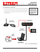
CHAPTER 2 STARTING OUT Model 195C/M Hardware Configuration Technical Tips: The following steps should be completed to begin configuration of the ESTeem Model 195C/M: 1. Connect the antenna cable to the TNC connection on the ESTeem Model 195C/M (Figure 1). 2. Connect the power supply and Ethernet cable to the ESTeem and proceed to Chapter 3 to begin programming. 1. Configure the Model 195C/M prior to mounting. 2. Attach antenna to the Model 195C/M before powering up.
CHAPTER 3 EXAMPLE APPLICATIONS Modes Of Operation The ESTeem Model 195C and 195M are sophisticated wireless networking devices that can be configured for multiple serial and Ethernet interfaces. Determining the correct mode of operation for the ESTeem is the first step in creating a reliable wireless network. This chapter will explain each mode of operation, provide example applications and detailed programming information for each mode. Please review the following modes of operations.
CHAPTER 3 EXAMPLE APPLICATIONS Figure 2: Point to Point with Repeater Revised: 10 Feb 14 3-2 EST P/N AA107-195CM
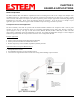
CHAPTER 3 EXAMPLE APPLICATIONS Transparent Multipoint Application The ESTeem 195C and 195M can be configured multipoint transparent operation (Figure 3). Similar to point to point applications, the 195C/M can support multiple serial data interfaces (RS-232, RS-422, RS-485 or Ethernet) on either end of the wireless link. These wireless links are independent of each other and configurable.
CHAPTER 3 EXAMPLE APPLICATIONS PLC Emulation Applications The ESTeem 195C and 195M can support PLC based networks in both point to point and multipoint applications. The PLC emulation driver allows the ESTeem to identify the destination address in the PLC message block and change the ESTeem destination address to match. This PLC emulation allows the ESTeem 195C/M to support multiple repeaters in a network (Figure 4).
CHAPTER 3 EXAMPLE APPLICATIONS Programming Examples Once the mode of operation for the ESTeem has been determined, you are now ready to program the Model 195C or 195M for use. ESTeem has created a simplified programming utility call the 195 Narrow Band Configuration Tool. This configuration utility will be used in all the following programming examples. For detailed instructions on installing the configuration utility and advanced operation, please refer to Chapter 6 of this User’s Manual.
CHAPTER 3 EXAMPLE APPLICATIONS Point to Point Transparent Example 1 (Figure 1) (2) ESTeem Model 195C Transparent RS-232 Wireless Link 465.500 MHz at 2 Watts Output Main Office Address – 172.16.10.182 Remote Site Address – 172.16.10.183 Technical Tip: The unit address of the ESTeem 195C or 195M is the last octet of the IP address. This single address is used when configuring the destination and routing. Example – Main Address IP = 172.16.10.182. Unit address = 182.
CHAPTER 3 EXAMPLE APPLICATIONS The above software commands can be adjusted in the “All” commands radial or found in their individual sections such as “Interface” and “Radio” (Figure 8). Figure 8: Interface and Radio Configuration Pages Once all the above software commands are adjusted to their correct parameters, press the Write Config button to send the changes to the 195C or 195M. The modem will reset and be ready for operation on the selected serial port.
CHAPTER 3 EXAMPLE APPLICATIONS Point to Point Transparent Example 2 (Figure 2) Technical Tip: The unit address of the ESTeem 195C or 195M is the last octet of the IP address. This single address is used when configuring the destination and routing. Example – Main Address IP = 172.16.10.182. Unit address = 182. (3) ESTeem Model 195C Transparent RS-232 Wireless Link 465.500 MHz at 2 Watts Output Main Office Address – 172.16.10.182 Remote Site Address – 172.16.10.183 Repeater Site Address – 172.16.10.
CHAPTER 3 EXAMPLE APPLICATIONS Multipoint Transparent Example 1 (Figure 3) Technical Tip: The unit address of the ESTeem 195C or 195M is the last octet of the IP address. This single address is used when configuring the destination and routing. Example – Main Address IP = 172.16.10.182. Unit address = 182. (4) ESTeem Model 195C Transparent RS-485 Wireless Link 465.500 MHz at 2 Watts Output Main Office Address – 172.16.10.182 Remote Site Addresses – 172.16.10.183-172.16.10.
CHAPTER 3 EXAMPLE APPLICATIONS PLC Emulation Example 1 (Figure 4) Technical Tip: The unit address of the ESTeem 195C or 195M is the last octet of the IP address. This single address is used when configuring the destination and routing. Example – Main Address IP = 172.16.10.182. Unit address = 182. (6) ESTeem Model 195C Rockwell DF1 Half-Duplex (BCC) Emulation 465.500 MHz at 2 Watts Output Main Office Address – 172.16.10.182 Remote Site Addresses – 172.16.10.183-172.16.10.
CHAPTER 3 EXAMPLE APPLICATIONS PLC Emulation Command Lists When using the PLC emulation driver at the Master site, you may notice many of the software commands required for transparent operation are not required. The following are a summary of the software command necessary to configure the ESTeem 195C or 195M for specific PLC emulation drivers. Figure 9 shows the drop down list of available PLC emulation drivers.
CHAPTER 4 REPEATING FEATURES Any ESTeem Model 195C or 195M in the wireless network can be used as a repeater to reach a remote location. Manually entering repeater routes in a terminal for testing a connection (connect command) or remote programming (program command) is as simple as adding the routing in the address with the repeaters identified by commas.
CHAPTER 4 REPEATING FEATURES Route 2: Refer to Figure 1 and find Route 2. This route has a repeater address of 3 and addresses 20 through 21 use this route. Note: Although address 20 is a repeater for another route, it requires an ESTeem address and needs to be counted. Type 3 in the first repeater block, 20 in the first address field and 21 in the second (Figure 4). Figure 4: Route 2 Configuration Route 3: Refer to Figure 1, Route 3 and notice there are two repeaters in this route (addresses 3 and 20).
CHAPTER 4 REPEATING FEATURES Reading Route and Append Tables To find the saved route and append tables in an ESTeem 195C or 195M click on the Route/Append tab of the Model 195 Narrowband Configuration Utility and press the Read Tables button. Figure 7 displays the saved Routes and Appends for the wireless network shown in Figure 1.
CHAPTER 5 ETHERNET APPLICATIONS The ESTeem Model 195C and 195M have a Full and Half-Duplex Auto-negotiation interface supporting both 10 Mbps and 100 Mbps (10/100BaseT). The port is compatible with TIA/EIA-568B cable configuration (Figure 1). The Ethernet port is used for both programming the Model 195C/M and data transfer.
CHAPTER 5 ETHERNET APPLICATIONS Ethernet Bridge Mode The mode of operation for transfer of Ethernet data over an ESTeem 195C or 195M wireless network is the Ethernet Bridge Mode. This mode is primarily used to gather data from remote Ethernet devices such as RTU’s or PLC’s in supervisory control networks (SCADA). Bridging Ethernet networks with these narrowband wireless modems will not work.
CHAPTER 5 ETHERNET APPLICATIONS The configuration of the Route and Append list for an Ethernet bridge is very similar to the configuration for repeaters. The main difference is that the last octet of IP addresses will be used in a “Group” in the append table to identify which address is the ESTeem 195C/M. The ESTeem address in the group will always be the lowest number (see examples below).
CHAPTER 6 UTILITIES & FEATURES 195 Narrowband Configuration Utility The ESTeem Narrowband Configuration Utility will allow easy access to the configuration, monitoring and diagnostics for the ESTeem Model 195C and 195M. Installation To install the Discovery Utility on your computer, insert the Resource Disk in your CD drive. Note: The ESTeem Resource Disk is a stand-alone copy of the ESTeem Web site (Figure 1). Navigation of the Resource Disk is as simple as using your web browser.
CHAPTER 6 UTILITIES & FEATURES 3. The Configuration Utility is a Java™ based application compatible with any computer operating system (Window, Linux, etc). The application requires two (2) additional support files to operate: Java – Downloadable from http://www.java.com. The version required will be based upon your operating system. Note: The installation and updates from Java may try and install additional web browser toolbars. Uncheck the optional installation if they are not desired.
CHAPTER 6 UTILITIES & FEATURES 6. The ESTeem 195C/M will be displayed (Figure 4). If the ESTeem 195C/M is not on the same IP subnet as the computer, double click on the IP, Netmask or Gateway and make the necessary changes. Press the Apply Changes button when complete. 7. If changes were made to the IP address you will need to press the Discover EST Modems button again to show the changes. Right-mouse click on the ESTeem 195C/M and select Configure Radio button to begin programming.
CHAPTER 6 UTILITIES & FEATURES Modbus Monitoring The ESTeem 195C/M support ModbusTCP protocol for access to multiple operating parameters in the wireless modem. Receive signal strengths, background noise, input voltage, and packet transmissions are a few of the parameter available though the open ModbusTCP protocol. There are multiple methods for extracting the data from the 195C/M, but the Configuration Utility has simple data interface on the Configuration Tab.
CHAPTER 6 UTILITIES & FEATURES Example of using modpoll utility with 195 narrow band series modpoll -l 2000 -o 2 -m tcp -r 1000 -c 19 -t3:float -a 101 172.18.9.
CHAPTER 6 UTILITIES & FEATURES Update Firmware The 195C and 195M firmware is updated by pressing the Update Firmware button on the Firmware tab of the utility. The firmware version is tied to the release version of the utility and is listed below the address (Figure 10). The release of any new firmware version will be listed on the products web site address: http://www.esteem.com/products/195c-450-470-mhz-serial.html http://www.esteem.com/products/195m-150-174-mhz-serial.
CHAPTER 7 ANTENNA SETUPS ESTeem offers different types of antennas ranging from ¼ wave to 5/8 wave in physical size. The user choice is dependent on the application. Communications in the VHF and UHF bands are normally over "Line of Sight (LOS)". Looking from the antenna of one wireless modem you must be able to see the antenna of the wireless modem you wish to communicate with. If a large object obstructs the line of sight view it is unlikely that satisfactory communications will result.
CHAPTER 7 ANTENNA SETUPS Weather Proofing Coax Connections 1. Lightly coat the threads of the connectors with silicone lubricant prior to assembly (See Note 1) and hand tighten. Make sure to use the silicon sparingly so when assembled, any excess does not get on center conductor. Care should be taken not to get any lubricant on the center conductor. 2. Wrap the connector assembly with a non-adhesive silicone tape, EST part number AA243, for weather proofing (See Note 2 and instructions below).
CHAPTER 7 ANTENNA SETUPS Revised 4 Feb 14 7-3 EST P/N AA107-195CM
CHAPTER 7 ANTENNA SETUPS Revised 4 Feb 14 7-4 EST P/N AA107-195CM
CHAPTER 7 ANTENNA SETUPS Revised 4 Feb 14 7-5 EST P/N AA107-195CM
CHAPTER 7 ANTENNA SETUPS Revised 4 Feb 14 7-6 EST P/N AA107-195CM
APPENDIX A SOFTWARE COMMANDS Listed below in alphabetical order are the definitions of the ESTeem software commands. All software commands are entered lowercase. The commands are displayed below with the full software command and the shorted command underlined. ? or help help Displays the modem information and sub help menus. help all help change help control help plc help radio help interface help setup help system help 192compat Displays all commands switches and arguments.
APPENDIX A SOFTWARE COMMANDS This command sets the baud rate for the serial device interface (SDI). The other commands are the data bits, parity and stop bits cert This command will display the certification for the ESTeem 195C/M. The FCC ID, Canadian DOC ID and serial number of the modem will be displayed. chspace (1-2) This command will set the channel spacing for the ESTeem 195C/M. 1 = 6.25 kHz channel spacing 2 = 12.5 kHz channel spacing Factory default = 2 (12.
APPENDIX A SOFTWARE COMMANDS This command enables the Ethernet bridge on the ESTeem 195C/M. See Chapter 6 for full details. Factory default = off. on: Enabled off: Disabled factory The factory default command. The execution of this command causes the ESTeem to restore the command table values from factory values that are stored permanently in memory. This will allow the user the ability to restore the ESTeem to factory conditions during testing or set-up. frequency (150.000-174.000) or (450.000-470.
APPENDIX A SOFTWARE COMMANDS netmask (*IP Address Netmask) The netmask command sets the IP netmask for the ESTeem 195C/M. This command is used in conjunction with the ip_addr and gw_addr commands to complete IP address for the ESTeem. Factory default = 255.255.0.0 network (0-255) Network identification code. This is used to program a common code for all modems in the customers network so that another facility on your frequency using the same addresses will not interfere with your equipment.
APPENDIX A SOFTWARE COMMANDS program (1-254,1-254,1-254,1-254) This command is used to remote program another ESTeem unit. Example prog 10 (Unit 10 is the address of the remote unit). Remote programming can be completed through repeaters. When a connection has been made with the remote ESTeem the RPG: prompt will appear. The RPG: prompt is the command prompt of the remote modem. radio (on/off) The radio transmitter enable command.
APPENDIX A SOFTWARE COMMANDS The save command. The execution of this command stores the current command values and switches. Note: Please wait approximately two seconds after executing the SAVE command before turning off power to the ESTeem. s/n Serial Number command. When executed from the Command Model will output the ESTeem serial number of the unit that is defined at the time of manufacturer. sdi Sets the serial device interface (sdi) for the ESTeem 195C/M.
APPENDIX A SOFTWARE COMMANDS Number of milliseconds the ESTeem 195C/M will wait after receiving serial or Ethernet data packet before transmitting to remote. Factory default = 1. xhflow (0-1) This command enables hardware flow control. Factory default = 0 (Disabled). 0 = Disabled. 1 = Enabled. version This command will display the current firmware version, boot loader version and firmware CRC. vinaux This command will display the DC voltage input in the auxiliary power is used.
APPENDIX B INTERFACE PORTS Interface Ports The ESTeem Model 195C and 195M have multiple data ports available for use. Each data interface is accessible through one of the four RJ-45 ports in the front panel of the Model 195C/M (Figure 1). During the configuration of the modem, one of these ports is configured as the serial data interface (SDI). All data ports not configured as the SDI are available for console programming.
APPENDIX B INTERFACE PORTS Ethernet Port (Port 2) The ESTeem Model 195C and 195M have a Full and Half-Duplex Auto-negotiation interface supporting both 10 Mbps and 100 Mbps (10/100BaseT). The port is compatible with TIA/EIA-568B cable configuration (Figure 2). A standard Ethernet patch cable (AA09.2) can be used to interface the 195C/M to a computer. The Ethernet port is used for both programming the Model 195C/M and data transfer.
APPENDIX B INTERFACE PORTS RS-485 and RS-422 Data Ports (Ports 1 and 2) The ESTeem Model 195C/M have a single, two-wire RS-485 interface in Port 1 and a single, four-wire RS-422 interface in Port 2. To ease access to these ports the AA066 (Figure 3) cable adapter is available. The RJ-45 interface can be inserted into either Port 1 (RS-485) or Port 2 (RS-422) and the corresponding signal lines (Figure 1) can be inserted in the screw terminals.
APPENDIX C MODEL 192 INTEGRATION Model Series 192 Integration Technical Tip: The ESTeem Model The ESTeem Model 195C and 195M were designed to be downward compatible 192 network MUST be configured for with the legacy ESTeem Model 192 series of wireless modems. The Model 192 narrow band (12.5 kHz) operation series had been in production since 1996 with several generational changes in the before Model 195C/M integration. product lifespan.
APPENDIX D FCC/DOC INFORMATION INFORMATION TO USERS WARNING: This equipment has been tested and found to comply with the limits for a Class A digital device, pursuant to Part 15 of the FCC Rules. These limits are designed to provide reasonable protection against harmful interference when the equipment is operated in a commercial environment.
APPENDIX D FCC/DOC INFORMATION RF EXPOSURE WARNING: A minimum separation must be maintained between the user and nearby antenna at the following distances: EXPOSITION RF AVERTISSEMENT: Un minimum de séparation doit être maintenue entre l'utilisateur et à proximité antenne aux distances suivantes: Radio Model Antenna Model/Gain FCC Minimum Separation Distance Controlled Environment 195C 9 Watts Max AA19C (0 dBd) 35 cm 0.35 m 77 cm 0.77 m 195C 9 Watts Max AA20C.1 (3.2 dBd) 50 cm 0.5 m 111 cm 1.
APPENDIX D FCC/DOC INFORMATION North American Power Density Limits FCC Part 47 Section 1.1309 Limits (Controlled Environments / Occupational Exposure) 150-174 MHz (195M) 1 mW/cm² 450 MHz (195C) 1.5 mW/cm² FCC Part 47 Section 1.1309 Limits (General Population / Uncontrolled exposure) 150-174 MHz (195M) 0.2 mW/cm² 450 MHz (195C) 0.
APPENDIX D FCC/DOC INFORMATION FEDERAL COMMUNICATIONS COMMISSION FIELD OFFICES ALASKA 1011 E. Tudor Rd. Rm 240 Box 2955 Anchorage, AK 99510 CALIFORNIA Interstate Office Park 4542 Ruffner St., Room 370 San Diego, CA 92111-2216 Los Angeles Office (LA) Ceritos Corporate Tower 18000 Studebaker Rd., Room 660 Cerritos, CA 90701-3684 San Francisco Office (SF) 5653 Stoneridge Drive, Suite 105 Pleasanton, CA 94588-8543 COLORADO Denver Office (DV) 215 S. Wadsworth Blvd.
APPENDIX D FCC/DOC INFORMATION FEDERAL COMMUNICATIONS COMMISSION FIELD OFFICES ALASKA 1011 E. Tudor Rd. Rm 240 Box 2955 Anchorage, AK 99510 CALIFORNIA Interstate Office Park 4542 Ruffner St., Room 370 San Diego, CA 92111-2216 Los Angeles Office (LA) Ceritos Corporate Tower 18000 Studebaker Rd., Room 660 Cerritos, CA 90701-3684 San Francisco Office (SF) 5653 Stoneridge Drive, Suite 105 Pleasanton, CA 94588-8543 COLORADO Denver Office (DV) 215 S. Wadsworth Blvd.
APPENDIX E 195C SPECIFICATIONS ESTeem 195C Specifications Transmiter/Receiver Frequency of Operation (Software Selectable) 450 to 470 Mhz (6.25Khz / 12.5 Khz Channel Spacing) Frequency Stability, -30C to +60C +/- 0.4ppm RF Data Rate @ 6.25Khz channel spacing 4.8Kbps RF Data Rate @ 12.5Khz channel spacing 9.6Kbps Tx Output Power (Software Adjustable) 0.
APPENDIX E 195C SPECIFICATIONS Antenna Specifications Model No: Antenna Type: Applications: Frequency: Polarization: Impedance: Gain: VSWR: Front To Back Ratio: Horizontal Beamwidth: Vertical Beamwidth: Antenna Material: Mounting Hardware: Antenna Connector: Antenna Envelope: Weight: Model No: Antenna Type: Applications: Frequency: Polarization: Impedance: Gain: VSWR: Front To Back Ratio: Horizontal Beamwidth: Vertical Beamwidth: Antenna Material: Mounting Hardware: Antenna Connector: Antenna Envelope: We
APPENDIX E 195C SPECIFICATIONS Antenna Specifications Model No: Antenna Type: Applications: Frequency: Polarization: Impedance: Gain: VSWR: Front To Back Ratio: Horizontal Beamwidth: Vertical Beamwidth: Antenna Material: Mounting Hardware: Antenna Connector: Maximum Power Input: Antenna Envelope: Windload (RWV): Weight: Revised: 27 Mar 14 AA202C.1 Directional, DC grounded, 5 element yagi. Fixed base. 440 to 470 MHz Vertical or Horizontal 50 ohms 9 dBd < 1.
APPENDIX G 195M SPECIFICATIONS ESTeem 195M Specifications Transmiter/Receiver Frequency of Operation (Software Selectable) 150 to 174 Mhz (6.25Khz / 12.5 Khz Channel Spacing) Frequency Stability, -30C to +60C +/- 0.2ppm RF Data Rate @ 6.25Khz channel spacing 4.8Kbps RF Data Rate @ 12.5Khz channel spacing 9.6Kbps Tx Output Power (Software Adjustable) 0.
APPENDIX F 210M SPECIFICATIONS Antenna Specifications Model No: Antenna Type: Applications: Frequency: Polarization: Impedance: Gain: VSWR: Front To Back Ratio: Horizontal Beamwidth: Vertical Beamwidth: Antenna Material: Mounting Hardware: Antenna Connector: Antenna Envelope: Weight: AA19M Omni-Directional, ½ Wave over ¼ Wave Mobile Mount. 150-174 MHz Vertical 50 ohms 0 dBd < 1.5 to 1 n/a n/a 60 degrees Rubber duck whip. Magnetic base. TNC with 12 feet integral RG-58 cable. 11 in. length. Magnetic base 3.
APPENDIX F 210M SPECIFICATIONS Antenna Specifications Model No: Antenna Type: Applications: Frequency: Polarization: Impedance: Gain: VSWR: Front To Back Ratio: Horizontal Beamwidth: Vertical Beamwidth: Antenna Material: Mounting Hardware: AA202M Directional, 6 element yagi. Fixed base mounting. 150 to 174 MHz Vertical or Horizontal 50 ohms 8 dBd < 1.2:1 12-18 dB 80 degrees 58 degrees .250” – 6061-T6 Aluminum Heavy duty U bolts for mounting up to 2 1/8 in. pipe with right angle mount or direct panel mount.