
User's Manual Part 2

CHAPTER 5
REPEATING FEATURES
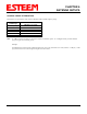
Revised: 25 Jun 04 5-1 EST P/N AA107G
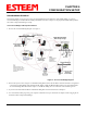
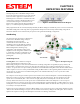
The Repeating Feature in the Model 195Eg is used to
increase the wireless network area of coverage for both
indoor and outdoor applications without the cost of
hardwiring the Access Points to a common LAN. This
custom feature is unique to the Model 195Eg because
conventional 802.11b/g Access Points have to be
interfaced to a common network either by hardwire, see
Figure 1, or a dedicated point to point RF backbone.
When programmed in the Access Point (AP) Repeater Mode, the Model 195Eg will automatically create a wireless network with
other Model 195Eg units in radio range that are programmed in AP Repeater mode and setup with matching configurations.
This feature adds the increased functionality of repeaters to the typical Ethernet Bridge configuration.
AutoRouting
One of the most powerful features of the Repeater
Feature mode is the Model 195Eg’s ability to
automatically calculate all possible
communication routes in the network. The
AutoRoute feature will automatically establish
wireless Ethernet communication paths to each
Model 195Eg that has a matching setup
configuration. This automatic routing greatly
simplifies network configuration and also creates
a “self healing” network by sending data on an
alternate route, if available, upon failure of the
primary path.
AutoRouting Process
Listening Phase. Once a modem is configured
for Access Point Repeater mode and reset, the
Model 195Eg will begin to search out all modems that have a matching configuration setup (SSID, Frequency Channel, AP
Repeater Mode = ON and Security Codes). The first step in the routing process is sending out and listening for “repeater
beacons”. A repeater beacon is a special radio packet that is sent from the Model 195Eg that contains the unit’s MAC address.
When a repeater beacon is received by another Model 195Eg, the MAC address of the originating modem is added to its own
repeater beacons. A route between two Model 195Eg units can be established when they receive a repeater beacon that
contains their own address.
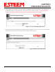
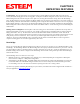
For example let’s look at Figure 2 and the repeater beacons and the route created from Pump Site C and Tank Site B(Repeater).
Pump Site C sends a repeater beacon containing its MAC address over the radio network. The only site that receives this
repeater beacon is Tank Site B (Note – there is no Line-of-sight (LOS) between from Pump Site C to the other sites in the
network). When Tank Site B receives the repeater beacon it adds the MAC address from Pump Site C to its own repeater
beacon and sends it out. This new repeater beacon from Tank Site B (Now containing Pump Site C’s MAC address) is received
at Pump Site C and a route is established. Pump Site C then adds the MAC address for Tank Site B in its repeater beacon, which
is eventually received by Tank Site B.
Repeater beacons will continually be sent from a Model 195Eg every 2 seconds as long as it is configured in AP Repeater mode.
This will allow the Model 195Eg to recognize new sites into the network and any changes to the radio paths. These continued
updates in the repeater beacons give the AP Repeater network the “self-healing” characteristic.
Figure 1: Conventional Access Point Diagram
Figure 2: AP Repeater Diagram